
An amplifier, electronic amplifier or (informally) amp is an electronic device that can increase the power of a signal. It is a two-port electronic circuit that uses electric power from a power supply to increase the amplitude of a signal applied to its input terminals, producing a proportionally greater amplitude signal at its output. The amount of amplification provided by an amplifier is measured by its gain: the ratio of output voltage, current, or power to input. An amplifier is a circuit that has a power gain greater than one.

An operational amplifier is a DC-coupled high-gain electronic voltage amplifier with a differential input and, usually, a single-ended output. In this configuration, an op amp produces an output potential that is typically 100,000 times larger than the potential difference between its input terminals. The operational amplifier traces its origin and name to analog computers, where they were used to perform mathematical operations in linear, non-linear, and frequency-dependent circuits.

In electronics, a common-base amplifier is one of three basic single-stage bipolar junction transistor (BJT) amplifier topologies, typically used as a current buffer or voltage amplifier.

A differential amplifier is a type of electronic amplifier that amplifies the difference between two input voltages but suppresses any voltage common to the two inputs. It is an analog circuit with two inputs and and one output , in which the output is ideally proportional to the difference between the two voltages:

In electronics, a voltage divider (also known as a potential divider) is a passive linear circuit that produces an output voltage (Vout) that is a fraction of its input voltage (Vin). Voltage division is the result of distributing the input voltage among the components of the divider. A simple example of a voltage divider is two resistors connected in series, with the input voltage applied across the resistor pair and the output voltage emerging from the connection between them.

A buffer amplifier is one that provides electrical impedance transformation from one circuit to another, with the aim of preventing the signal source from being affected by whatever currents that the load may impose. The signal is 'buffered from' load currents. Two main types of buffer exist: the voltage buffer and the current buffer.

In electronics, a common-emitter amplifier is one of three basic single-stage bipolar-junction-transistor (BJT) amplifier topologies, typically used as a voltage amplifier. It offers high current gain, medium input resistance and a high output resistance. The output of a common emitter amplifier is 180 degrees out of phase to the input signal.

In electronics, a common collector amplifier is one of three basic single-stage bipolar junction transistor (BJT) amplifier topologies, typically used as a voltage buffer.
A current mirror is a circuit designed to copy a current through one active device by controlling the current in another active device of a circuit, keeping the output current constant regardless of loading. The current being "copied" can be, and sometimes is, a varying signal current. Conceptually, an ideal current mirror is simply an ideal inverting current amplifier that reverses the current direction as well. Or it can consist of a current-controlled current source (CCCS). The current mirror is used to provide bias currents and active loads to circuits. It can also be used to model a more realistic current source.

The output impedance of an electrical network is the measure of the opposition to current flow (impedance), both static (resistance) and dynamic (reactance), into the load network being connected that is internal to the electrical source. The output impedance is a measure of the source's propensity to drop in voltage when the load draws current, the source network being the portion of the network that transmits and the load network being the portion of the network that consumes.

A current source is an electronic circuit that delivers or absorbs an electric current which is independent of the voltage across it.
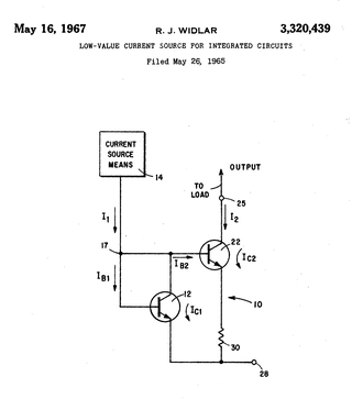
A Widlar current source is a modification of the basic two-transistor current mirror that incorporates an emitter degeneration resistor for only the output transistor, enabling the current source to generate low currents using only moderate resistor values.
The cascode is a two-stage amplifier that consists of a common-emitter stage feeding into a common-base stage.
This article illustrates some typical operational amplifier applications. A non-ideal operational amplifier's equivalent circuit has a finite input impedance, a non-zero output impedance, and a finite gain. A real op-amp has a number of non-ideal features as shown in the diagram, but here a simplified schematic notation is used, many details such as device selection and power supply connections are not shown. Operational amplifiers are optimised for use with negative feedback, and this article discusses only negative-feedback applications. When positive feedback is required, a comparator is usually more appropriate. See Comparator applications for further information.
A Wilson current mirror is a three-terminal circuit that accepts an input current at the input terminal and provides a "mirrored" current source or sink output at the output terminal. The mirrored current is a precise copy of the input current. It may be used as a Wilson current source by applying a constant bias current to the input branch as in Fig. 2. The circuit is named after George R. Wilson, an integrated circuit design engineer who worked for Tektronix. Wilson devised this configuration in 1967 when he and Barrie Gilbert challenged each other to find an improved current mirror overnight that would use only three transistors. Wilson won the challenge.

A clamper is an electronic circuit that fixes either the positive or the negative peak excursions of a signal to a defined voltage by adding a variable positive or negative DC voltage to it. The clamper does not restrict the peak-to-peak excursion of the signal (clipping); it moves the whole signal up or down so as to place its peaks at the reference level.
In the field of electronics, a technique where part of the output of a system is used at startup can be described as bootstrapping.

In electronics, biasing is the setting of DC operating conditions of an active device in an amplifier. Many electronic devices, such as diodes, transistors and vacuum tubes, whose function is processing time-varying (AC) signals, also require a steady (DC) current or voltage at their terminals to operate correctly. This current or voltage is called bias. The AC signal applied to them is superposed on this DC bias current or voltage.
Bipolar transistors must be properly biased to operate correctly. In circuits made with individual devices, biasing networks consisting of resistors are commonly employed. Much more elaborate biasing arrangements are used in integrated circuits, for example, bandgap voltage references and current mirrors. The voltage divider configuration achieves the correct voltages by the use of resistors in certain patterns. By selecting the proper resistor values, stable current levels can be achieved that vary only little over temperature and with transistor properties such as β.

A nullor is a theoretical two-port network consisting of a nullator at its input and a norator at its output. Nullors represent an ideal amplifier, having infinite current, voltage, transconductance and transimpedance gain. Its transmission parameters are all zero, that is, its input–output behavior is summarized with the matrix equation


