
The electrical resistance of an object is a measure of its opposition to the flow of electric current. Its reciprocal quantity is electrical conductance, measuring the ease with which an electric current passes. Electrical resistance shares some conceptual parallels with mechanical friction. The SI unit of electrical resistance is the ohm, while electrical conductance is measured in siemens (S).
In fluid mechanics, the center of pressure is the point on a body where a single force acting at that point can represent the total effect of the pressure field acting on the body. The total force vector acting at the center of pressure is the surface integral of the pressure vector field across the surface of the body. The resultant force and center of pressure location produce an equivalent force and moment on the body as the original pressure field.

Flight dynamics is the science of air vehicle orientation and control in three dimensions. The three critical flight dynamics parameters are the angles of rotation in three dimensions about the vehicle's center of gravity (cg), known as pitch, roll and yaw. These are collectively known as aircraft attitude, often principally relative to the atmospheric frame in normal flight, but also relative to terrain during takeoff or landing, or when operating at low elevation. The concept of attitude is not specific to fixed-wing aircraft, but also extends to rotary aircraft such as helicopters, and dirigibles, where the flight dynamics involved in establishing and controlling attitude are entirely different.

In mathematics, the beta function, also called the Euler integral of the first kind, is a special function that is closely related to the gamma function and to binomial coefficients. It is defined by the integral
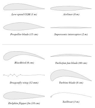
An airfoil or aerofoil is a streamlined body that is capable of generating significantly more lift than drag. Wings, sails and propeller blades are examples of airfoils. Foils of similar function designed with water as the working fluid are called hydrofoils.

Projectile motion is a form of motion experienced by an object or particle that is projected in a gravitational field, such as from Earth's surface, and moves along a curved path under the action of gravity only. In the particular case of projectile motion on Earth, most calculations assume the effects of air resistance are passive.
In rotordynamics, the rigid rotor is a mechanical model of rotating systems. An arbitrary rigid rotor is a 3-dimensional rigid object, such as a top. To orient such an object in space requires three angles, known as Euler angles. A special rigid rotor is the linear rotor requiring only two angles to describe, for example of a diatomic molecule. More general molecules are 3-dimensional, such as water, ammonia, or methane.
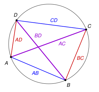
In Euclidean geometry, Ptolemy's theorem is a relation between the four sides and two diagonals of a cyclic quadrilateral. The theorem is named after the Greek astronomer and mathematician Ptolemy. Ptolemy used the theorem as an aid to creating his table of chords, a trigonometric table that he applied to astronomy.
Gnomonics is the study of the design, construction and use of sundials.

The NACA airfoil series is a set of standardized airfoil shapes developed by this agency, which became widely used in the design of aircraft wings.

In aerodynamics, the pitching moment on an airfoil is the moment produced by the aerodynamic force on the airfoil if that aerodynamic force is considered to be applied, not at the center of pressure, but at the aerodynamic center of the airfoil. The pitching moment on the wing of an airplane is part of the total moment that must be balanced using the lift on the horizontal stabilizer. More generally, a pitching moment is any moment acting on the pitch axis of a moving body.
Photon polarization is the quantum mechanical description of the classical polarized sinusoidal plane electromagnetic wave. An individual photon can be described as having right or left circular polarization, or a superposition of the two. Equivalently, a photon can be described as having horizontal or vertical linear polarization, or a superposition of the two.
The Kutta–Joukowski theorem is a fundamental theorem in aerodynamics used for the calculation of lift of an airfoil translating in a uniform fluid at a constant speed so large that the flow seen in the body-fixed frame is steady and unseparated. The theorem relates the lift generated by an airfoil to the speed of the airfoil through the fluid, the density of the fluid and the circulation around the airfoil. The circulation is defined as the line integral around a closed loop enclosing the airfoil of the component of the velocity of the fluid tangent to the loop. It is named after Martin Kutta and Nikolai Zhukovsky who first developed its key ideas in the early 20th century. Kutta–Joukowski theorem is an inviscid theory, but it is a good approximation for real viscous flow in typical aerodynamic applications.
The Lanchester-Prandtl lifting-line theory is a mathematical model in aerodynamics that predicts lift distribution over a three-dimensional wing from the wing's geometry. The theory was expressed independently by Frederick W. Lanchester in 1907, and by Ludwig Prandtl in 1918–1919 after working with Albert Betz and Max Munk. In this model, the vortex bound to the wing develops along the whole wingspan because it is shed as a vortex-sheet from the trailing edge, rather than just as a single vortex from the wing-tips.
In flight dynamics, longitudinal stability is the stability of an aircraft in the longitudinal, or pitching, plane. This characteristic is important in determining whether an aircraft pilot will be able to control the aircraft in the pitching plane without requiring excessive attention or excessive strength.

The Vortex lattice method, (VLM), is a numerical method used in computational fluid dynamics, mainly in the early stages of aircraft design and in aerodynamic education at university level. The VLM models the lifting surfaces, such as a wing, of an aircraft as an infinitely thin sheet of discrete vortices to compute lift and induced drag. The influence of the thickness and viscosity is neglected.
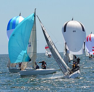
Forces on sails result from movement of air that interacts with sails and gives them motive power for sailing craft, including sailing ships, sailboats, windsurfers, ice boats, and sail-powered land vehicles. Similar principles in a rotating frame of reference apply to windmill sails and wind turbine blades, which are also wind-driven. They are differentiated from forces on wings, and propeller blades, the actions of which are not adjusted to the wind. Kites also power certain sailing craft, but do not employ a mast to support the airfoil and are beyond the scope of this article.
Blade element momentum theory is a theory that combines both blade element theory and momentum theory. It is used to calculate the local forces on a propeller or wind-turbine blade. Blade element theory is combined with momentum theory to alleviate some of the difficulties in calculating the induced velocities at the rotor.

Steady flight, unaccelerated flight, or equilibrium flight is a special case in flight dynamics where the aircraft's linear and angular velocity are constant in a body-fixed reference frame. Basic aircraft maneuvers such as level flight, climbs and descents, and coordinated turns can be modeled as steady flight maneuvers. Typical aircraft flight consists of a series of steady flight maneuvers connected by brief, accelerated transitions. Because of this, primary applications of steady flight models include aircraft design, assessment of aircraft performance, flight planning, and using steady flight states as the equilibrium conditions around which flight dynamics equations are expanded.

The dynamic stall is one of the hazardous phenomena on helicopter rotors, which can cause the onset of large torsional airloads and vibrations on the rotor blades. Unlike fixed-wing aircraft, of which the stall occurs at relatively low flight speed, the dynamic stall on a helicopter rotor emerges at high airspeeds or/and during manoeuvres with high load factors of helicopters, when the angle of attack(AOA) of blade elements varies intensively due to time-dependent blade flapping, cyclic pitch and wake inflow. For example, during forward flight at the velocity close to VNE, velocity, never exceed, the advancing and retreating blades almost reach their operation limits whereas flows are still attached to the blade surfaces. That is, the advancing blades operate at high Mach numbers so low values of AOA is needed but shock-induced flow separation may happen, while the retreating blade operates at much lower Mach numbers but the high values of AoA result in the stall.


