
An electrical insulator is a material whose internal electric charges do not flow freely; very little electric current will flow through it under the influence of an electric field. This contrasts with other materials, semiconductors and conductors, which conduct electric current more easily. The property that distinguishes an insulator is its resistivity; insulators have higher resistivity than semiconductors or conductors. The most common examples are non-metals.

A transmission medium is something that can mediate the propagation of signals for the purposes of telecommunication.

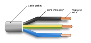
Zip-cord is a type of electrical cable with two or more conductors held together by an insulating jacket that can be easily separated simply by pulling apart. The term is also used with optical fiber cables consisting of two optical fibers joined in a similar manner. The design of zip-cord makes it easy to keep conductors that carry related electrical or optical signals together and helps avoid tangling of cables. Typical uses include lamp cord and speaker wire. Conductors may be identified by a color tracer on the insulation, or by a ridge molded into the insulation of one wire, or by a colored tracer thread inside the insulation. Zip cords are intended for use on portable equipment, and the US and Canadian electrical codes do not permit their use for permanently installed wiring of line-voltage circuits.
An electrical cable is an assembly of one or more wires running side by side or bundled, which is used to carry electric current.
Coaxial cable, or coax is a type of electrical cable that has an inner conductor surrounded by a tubular insulating layer, surrounded by a tubular conducting shield. Many coaxial cables also have an insulating outer sheath or jacket. The term coaxial comes from the inner conductor and the outer shield sharing a geometric axis. Coaxial cable was used in the first (1858) and following transatlantic cable installations, but its theory wasn't described until 1880 by English physicist, engineer, and mathematician Oliver Heaviside, who patented the design in that year.
Electrical breakdown or dielectric breakdown is when current flows through an electrical insulator when the voltage applied across it exceeds the breakdown voltage. This results in the insulator becoming electrically conductive. Electrical breakdown may be a momentary event, or may lead to a continuous arc if protective devices fail to interrupt the current in a power circuit.

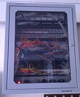
Electrical wiring is an electrical installation of cabling and associated devices such as switches, distribution boards, sockets, and light fittings in a structure.
A guy-wire, guy-line, or guy-rope, also known as simply a guy, is a tensioned cable designed to add stability to a free-standing structure. They are used commonly in ship masts, radio masts, wind turbines, utility poles, fire service extension ladders used in church raises and tents. A thin vertical mast supported by guy wires is called a guyed mast. Structures that support antennas are frequently of a lattice construction and are called "towers". One end of the guy is attached to the structure, and the other is anchored to the ground at some distance from the mast or tower base. The tension in the diagonal guy-wire, combined with the compression and buckling strength of the structure, allows the structure to withstand lateral loads such as wind or the weight of cantilevered structures. They are installed radially, usually at equal angles about the structure, in trios and quads. As the tower leans a bit due to the wind force, the increased guy tension is resolved into a compression force in the tower or mast and a lateral force that resists the wind load. For example, antenna masts are often held up by three guy-wires at 120° angles. Structures with predictable lateral loads, such as electrical utility poles, may require only a single guy-wire to offset the lateral pull of the electrical wires, at a spot where the wires change direction.

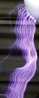
The term high voltage usually means electrical energy at voltages high enough to inflict harm on living organisms. Equipment and conductors that carry high voltage warrant particular safety requirements and procedures. In certain industries, high voltage means voltage above a particular threshold (see below). High voltage is used in electrical power distribution, in cathode ray tubes, to generate X-rays and particle beams, to demonstrate arcing, for ignition, in photomultiplier tubes, and in high power amplifier vacuum tubes and other industrial, military and scientific applications.

An overhead power line is a structure used in electric power transmission and distribution to transmit electrical energy across large distances. It consists of one or more conductors suspended by towers or poles. Since most of the insulation is provided by air, overhead power lines are generally the lowest-cost method of power transmission for large quantities of electric energy.
A power cable is an electrical cable, an assembly of one or more electrical conductors, usually held together with an overall sheath. The assembly is used for transmission of electrical power. Power cables may be installed as permanent wiring within buildings, buried in the ground, run overhead, or exposed.

An optical fiber is a flexible, transparent fiber made by drawing glass (silica) or plastic to a diameter slightly thicker than that of a human hair. Optical fibers are used most often as a means to transmit light between the two ends of the fiber and find wide usage in fiber-optic communications, where they permit transmission over longer distances and at higher bandwidths than electrical cables. Fibers are used instead of metal wires because signals travel along them with less loss; in addition, fibers are immune to electromagnetic interference, a problem from which metal wires suffer. Fibers are also used for illumination and imaging, and are often wrapped in bundles so they may be used to carry light into, or images out of confined spaces, as in the case of a fiberscope. Specially designed fibers are also used for a variety of other applications, some of them being fiber optic sensors and fiber lasers.

Knob-and-tube wiring is an early standardized method of electrical wiring in buildings, in common use in North America from about 1880 to the early 1940s. It consisted of single-insulated copper conductors run within wall or ceiling cavities, passing through joist and stud drill-holes via protective porcelain insulating tubes, and supported along their length on nailed-down porcelain knob insulators. Where conductors entered a wiring device such as a lamp or switch, or were pulled into a wall, they were protected by flexible cloth insulating sleeving called loom. The first insulation was asphalt-saturated cotton cloth, then rubber became common. Wire splices in such installations were twisted together for good mechanical strength, then soldered and wrapped with rubber insulating tape and friction tape, or made inside metal junction boxes.
Fiber-optic communication is a method of transmitting information from one place to another by sending pulses of infrared light through an optical fiber. The light forms an electromagnetic carrier wave that is modulated to carry information. Fiber is preferred over electrical cabling when high bandwidth, long distance, or immunity to electromagnetic interference are required. This type of communication can transmit voice, video, and telemetry through local area networks, computer networks, or across long distances.
An optical ground wire is a type of cable that is used in overhead power lines. Such cable combines the functions of grounding and communications. An OPGW cable contains a tubular structure with one or more optical fibers in it, surrounded by layers of steel and aluminum wire. The OPGW cable is run between the tops of high-voltage electricity pylons. The conductive part of the cable serves to bond adjacent towers to earth ground, and shields the high-voltage conductors from lightning strikes. The optical fibers within the cable can be used for high-speed transmission of data, either for the electrical utility's own purposes of protection and control of the transmission line, for the utility's own voice and data communication, or may be leased or sold to third parties to serve as a high-speed fiber interconnection between cities.
Telecom Electric Limited began life as a small project within the National Grid plc to determine the feasibility of running suspended optical fibre cables across the pylons of the high voltage power distribution network owned by the company. Three principal techniques were considered:
- Optical Ground Wire (OPGW), which replaced the earth wire that runs across the top of the pylons with a new cable that contained a tubular core in which up to 24 optical fibres could be placed. However this option was expensive to implement as it would mean writing off the capital value of the old earth cable many years before it was due to be replaced as part of the normal operation and maintenance cycle. Installation was also very expensive and methods to reduce costs in this area needed to be developed.
- Wrapped Fibre (WF), which involved a new technique of taking a variant of underground cable and wrapping it in a spiral fashion around the earth wire. A specially adapted machine was designed for the job to that made installation cost-effective. The challenge for the company however was how to protect the fibres in the cable from damage caused by starlings pecking at the cable sheath, which split open the cable exposing the fibres to water which would affect the optical transmission properties.
- All Dielectric Self Supporting (ADSS) Cable, which consisted of non-metallic suspension components and was already used on low voltage power distribution networks in various parts of the world. However, it was found that at 275 kV and 400 kV, the voltages used on the National Grid infrastructure, the electromagnetic fields from the power cables were sufficient to induce microsparks inside the cable that degraded the dielectric materials causing the cable to fail and collapse.

A fiber-optic cable, also known as an optical-fiber cable, is an assembly similar to an electrical cable, but containing one or more optical fibers that are used to carry light. The optical fiber elements are typically individually coated with plastic layers and contained in a protective tube suitable for the environment where the cable will be deployed. Different types of cable are used for different applications, for example, long distance telecommunication, or providing a high-speed data connection between different parts of a building.
Networking cables are networking hardware used to connect one network device to other network devices or to connect two or more computers to share printers, scanners etc. Different types of network cables, such as coaxial cable, optical fiber cable, and twisted pair cables, are used depending on the network's physical layer, topology, and size. The devices can be separated by a few meters or nearly unlimited distances.

A high-voltage cable is a cable used for electric power transmission at high voltage. A cable includes a conductor and insulation, and is suitable for being run underground or underwater. This is in contrast to an overhead line, which does not have insulation. High-voltage cables of differing types have a variety of applications in instruments, ignition systems, and alternating current (AC) and direct current (DC) power transmission. In all applications, the insulation of the cable must not deteriorate due to the high-voltage stress, ozone produced by electric discharges in air, or tracking. The cable system must prevent contact of the high-voltage conductor with other objects or persons, and must contain and control leakage current. Cable joints and terminals must be designed to control the high-voltage stress to prevent breakdown of the insulation. Often a high-voltage cable will have a metallic shield layer over the insulation, connected to the ground and designed to equalize the dielectric stress on the insulation layer.

Optical attached cable (OPAC) is a type of fibre optic cable that is installed by being attached to a host conductor along overhead power lines. The attachment system varies and can include wrapping, lashing or clipping the fibre optic cable to the host. Installation is typically performed using a specialised piece of equipment that travels along the host conductor from pole to pole or tower to tower, wrapping, clipping or lashing the fibre optic cable in place. Different manufacturers have different systems and the installation equipment, cable designs and hardware are not interchangeable.