Last updated Angle of incidence of an airplane wing on an airplane.
On fixed-wing aircraft, the angle of incidence (sometimes referred to as the mounting angle[1] or setting angle) is the angle between the chord line of the wing where the wing is mounted to the fuselage, and a reference axis along the fuselage (often the direction of minimum drag, or where applicable, the longitudinal axis). The angle of incidence is fixed in the design of the aircraft, and with rare exceptions, cannot be varied in flight.
The term can also be applied to horizontal surfaces in general (such as canards or horizontal stabilizers) for the angle they make relative the longitudinal axis of the fuselage.
The figure to the right shows a side view of an airplane. The extended chord line of the wing root (red line) makes an angle with the longitudinal axis (roll axis) of the aircraft (blue line). Wings are typically mounted at a small positive angle of incidence, to allow the fuselage to have a low angle with the airflow in cruising flight. Angles of incidence of about 6° are common on most general aviation designs. Other terms for angle of incidence in this context are rigging angle and rigger's angle of incidence.
The angle of incidence should not be confused with the angle of attack, which is the angle the wing chord presents to the airflow in flight. However some ambiguity in this terminology exists, as some engineering texts that focus solely on the study of airfoils and their medium may use either term when referring to angle of attack.[2]
On rotary–wing aircraft, the AoA (Angle of Attack) is the angle between the airfoil chord line and resultant relative wind. AoA is an aerodynamic angle. It can change with no change in the AoI (Angle of Incidence). Several factors may change the rotor blade AoA. Pilots control some of those factors; others occur automatically due to the rotor system design. Pilots adjust AoA through normal control manipulation; however, even with no pilot input AoA will change as an integral part of travel of the rotor blade through the rotor-disc. This continuous process of change accommodates rotary-wing flight. Pilots have little control over blade flapping and flexing, gusty wind, and/or turbulent air conditions. AoA is one of the primary factors determining amount of lift and drag produced by an airfoil.[3]
Notes
↑ Phillips, Warren F. (2010). Mechanics of Flight (2nded.). Wiley & Sons. ISBN978-0-470-53975-0.
↑ Kermode, A.C. (1972), Mechanics of Flight, Chapter 3, 8th edition, Pitman Publishing, London. ISBN0-273-31623-0
↑ "Fundamentals of Flight". Department of the Army. 7 May 2007. Retrieved 29 May 2019. This article incorporates text from this source, which is in the public domain.
Related Research Articles
A wing is a type of fin that produces lift while moving through air or some other fluid. Accordingly, wings have streamlined cross-sections that are subject to aerodynamic forces and act as airfoils. A wing's aerodynamic efficiency is expressed as its lift-to-drag ratio. The lift a wing generates at a given speed and angle of attack can be one to two orders of magnitude greater than the total drag on the wing. A high lift-to-drag ratio requires a significantly smaller thrust to propel the wings through the air at sufficient lift.
In fluid dynamics, a stall is a reduction in the lift coefficient generated by a foil as angle of attack increases. This occurs when the critical angle of attack of the foil is exceeded. The critical angle of attack is typically about 15°, but it may vary significantly depending on the fluid, foil, and Reynolds number.
In fluid dynamics, angle of attack is the angle between a reference line on a body and the vector representing the relative motion between the body and the fluid through which it is moving. Angle of attack is the angle between the body's reference line and the oncoming flow. This article focuses on the most common application, the angle of attack of a wing or airfoil moving through air.
Aircraft flight control surfaces are aerodynamic devices allowing a pilot to adjust and control the aircraft's flight attitude.
In aeronautics, dihedral is the angle between the left and right wings of an aircraft. "Dihedral" is also used to describe the effect of sideslip on the rolling of the aircraft.
A flap is a high-lift device used to reduce the stalling speed of an aircraft wing at a given weight. Flaps are usually mounted on the wing trailing edges of a fixed-wing aircraft. Flaps are used to reduce the take-off distance and the landing distance. Flaps also cause an increase in drag so they are retracted when not needed.
Aircraft flight mechanics are relevant to fixed wing and rotary wing (helicopters) aircraft. An aeroplane, is defined in ICAO Document 9110 as, "a power-driven heavier than air aircraft, deriving its lift chiefly from aerodynamic reactions on surface which remain fixed under given conditions of flight".
Retreating blade stall is a hazardous flight condition in helicopters and other rotary wing aircraft, where the retreating rotor blade has a lower relative blade speed, combined with an increased angle of attack, causing a stall and loss of lift. Retreating blade stall is the primary limiting factor of a helicopter's never exceed speed, VNE.
A vertical stabilizer or tail fin is the static part of the vertical tail of an aircraft. The term is commonly applied to the assembly of both this fixed surface and one or more movable rudders hinged to it. Their role is to provide control, stability and trim in yaw. It is part of the aircraft empennage, specifically of its stabilizers.
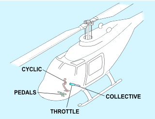
A helicopter pilot manipulates the helicopter flight controls to achieve and maintain controlled aerodynamic flight. Changes to the aircraft flight control system transmit mechanically to the rotor, producing aerodynamic effects on the rotor blades that make the helicopter move in a deliberate way. To tilt forward and back (pitch) or sideways (roll) requires that the controls alter the angle of attack of the main rotor blades cyclically during rotation, creating differing amounts of lift (force) at different points in the cycle. To increase or decrease overall lift requires that the controls alter the angle of attack for all blades collectively by equal amounts at the same time, resulting in ascent, descent, acceleration and deceleration.
An aircraft stabilizer is an aerodynamic surface, typically including one or more movable control surfaces, that provides longitudinal (pitch) and/or directional (yaw) stability and control. A stabilizer can feature a fixed or adjustable structure on which any movable control surfaces are hinged, or it can itself be a fully movable surface such as a stabilator. Depending on the context, "stabilizer" may sometimes describe only the front part of the overall surface.
A helicopter main rotor or rotor system is the combination of several rotary wings with a control system, that generates the aerodynamic lift force that supports the weight of the helicopter, and the thrust that counteracts aerodynamic drag in forward flight. Each main rotor is mounted on a vertical mast over the top of the helicopter, as opposed to a helicopter tail rotor, which connects through a combination of drive shaft(s) and gearboxes along the tail boom. The blade pitch is typically controlled by the pilot using the helicopter flight controls. Helicopters are one example of rotary-wing aircraft (rotorcraft). The name is derived from the Greek words helix, helik-, meaning spiral; and pteron meaning wing.
A rotorcraft or rotary-wing aircraft is a heavier-than-air aircraft with rotary wings or rotor blades, which generate lift by rotating around a vertical mast. Several rotor blades mounted on a single mast are referred to as a rotor. The International Civil Aviation Organization (ICAO) defines a rotorcraft as "supported in flight by the reactions of the air on one or more rotors".
An aircraft propeller, also called an airscrew, converts rotary motion from an engine or other power source into a swirling slipstream which pushes the propeller forwards or backwards. It comprises a rotating power-driven hub, to which are attached several radial airfoil-section blades such that the whole assembly rotates about a longitudinal axis. The blade pitch may be fixed, manually variable to a few set positions, or of the automatically variable "constant-speed" type.
The Bölkow Bo 46 was a West German experimental helicopter built to test the Derschmidt rotor system that aimed to allow much higher speeds than traditional helicopter designs. Wind tunnel testing showed promise, but the Bo 46 demonstrated a number of problems and added complexity that led to the concept being abandoned. The Bo 46 was one of a number of new designs exploring high-speed helicopter flight that were built in the early 1960s.
The cyclogyro, or cyclocopter, is an aircraft configuration that uses a horizontal-axis cyclorotor as a rotor wing to provide lift and sometimes also propulsion and control. In principle, the cyclogyro is capable of vertical take off and landing and hovering performance like a helicopter, while potentially benefiting from some of the advantages of a fixed-wing aircraft.
The wing configuration of a fixed-wing aircraft is its arrangement of lifting and related surfaces.
A rotor wing is a lifting rotor or wing which spins to provide aerodynamic lift. In general, a rotor may spin about an axis which is aligned substantially either vertically or side-to-side (spanwise). All three classes have been studied for use as lifting rotors and several variations have been flown on full-size aircraft, although only the vertical-axis rotary wing has become widespread on rotorcraft such as the helicopter.
The Feiro Dongó was a Hungarian side-by-side trainer biplane. It was notable for its high aspect ratio wings, aerodynamic clearness and high lift/drag ratio.
The Magni PM.2 Vittoria was an Italian experimental, single seat, parasol wing aircraft built in the mid-1920s. It had a large area aerofoil on each of its single wing bracing struts which could be rotated together or independently to give lift or drag.
This page is based on this Wikipedia article Text is available under the CC BY-SA 4.0 license; additional terms may apply. Images, videos and audio are available under their respective licenses.