Arching or compressive membrane action in reinforced concrete slabs

Last updated

Idealisation of arching action forces in laterally restrained slab Arching action in laterally restrained slab.svg
Idealisation of arching action forces in laterally restrained slab

Arching or compressive membrane action (CMA) in reinforced concrete slabs occurs as a result of the great difference between the tensile and compressive strength of concrete. Cracking of the concrete causes a migration of the neutral axis which is accompanied by in-plane expansion of the slab at its boundaries. If this natural tendency to expand is restrained, the development of arching action enhances the strength of the slab. The term arching action is normally used to describe the arching phenomenon in one-way spanning slabs and compressive membrane action is normally used to describe the arching phenomenon in two-way spanning slabs.

Contents

Background

Arching action forces in beam and slab bridge deck Arching action in bridge deck slab.png
Arching action forces in beam and slab bridge deck

The strength enhancing effects of arching action in reinforced concrete floors were first recognised near the beginning of last century. [1] However, it was not until the full scale destructive load tests by Ockleston [2] [3] on the Old Dental Hospital in Johannesburg that the extent of strength enhancement caused by arching action was really appreciated. In these tests, collapse loads of between 3 and 4 times those predicted by yield-line theory [4] were obtained.

Arching action (CMA) strength enhancement in laterally restrained slab strip Arching action strength enhancement.png
Arching action (CMA) strength enhancement in laterally restrained slab strip

Approaches to treatment of arching action (CMA)

Since the 1950s there have been several attempts to develop theories for arching action in both one and two-way slabs. [5] [6] [7] One of the principal approaches to membrane action was that due to Park [8] which has been used as a basis for many studies into arching action in slabs. Park's approach was based on rigid plastic slab strip theory, and required the assumption of a critical deflection of one half of the slab depth at failure. Park's approach was later extended by Park and Gamble [9] in their method for predicting the plastic load-deformation response of laterally restrained slabs.

In 1971, the American Concrete Institute [10] produced a special publication which presented the most recent research, to that time, on arching and compressive membrane action in reinforced concrete slabs.

A comprehensive review of the literature and studies of both rigid-plastic and elastic-plastic approaches to arching have been compiled by Braestrup [11] and Braestrup and Morley. [12] Lahlouh and Waldron [13] were some of the earliest researchers to achieve a degree of success in finite element modelling of the phenomenon. In 1993, Kuang and Morley [14] presented a plasticity approach which included the effect of compressive membrane action on the punching shear strength of laterally restrained concrete slabs.

United Kingdom approach to CMA in bridge deck design

In the United Kingdom, the method developed by Kirkpatrick, Rankin & Long [15] in 1984 and substantiated by testing a full-scale bridge in 1986 [16] first led to the introduction of new rules for the economic design of reinforced concrete beam and slab bridge decks in Northern Ireland. [17] The concept and method were later incorporated, by the United Kingdom Highways Agency, into the UK design manual for roads and bridges, BD 81/02, 'Use of Compressive Membrane Action in Bridge Decks'. [18] Use of this CMA methodology normally results in substantial savings in reinforcement in the slab of a beam and slab bridge deck, provided certain limitations and boundary conditions are satisfied.

Punching failure in beam and slab bridge deck Punching failure in beam and slab bridge deck.png
Punching failure in beam and slab bridge deck
Top surface crack pattern of punching failure zone in model bridge deck test Bridge deck - punching failure top cracking.png
Top surface crack pattern of punching failure zone in model bridge deck test
Bottom surface crack pattern of punching failure zone in model bridge deck test Bridge deck - punching failure bottom cracking.png
Bottom surface crack pattern of punching failure zone in model bridge deck test

Kirkpatrick, Rankin & Long's [15] approach to the prediction of the enhanced punching strength of bridge deck slabs was based on the punching shear prediction equation derived by Long [20] for the shear mode of punching failure, combined with an effective reinforcement ratio, which represented the arching action strength enhancement. The effective reinforcement ratio was determined from the maximum arching moment of resistance in a rigidly restrained concrete slab, which Rankin [21] had derived for laterally restrained concrete slabs from McDowell, McKee and Sevin's [22] arching action deformation theory for masonry walls. The derivation of the maximum arching moment of resistance of laterally restrained concrete bridge deck slabs utilised Rankin's [21] idealised elastic-plastic stress-strain criterion for concrete, valid for concrete cylinder strengths up to at least 70N/mm2, which he had derived on the basis of Hognestad, Hanson and McHenry's [23] ultimate parabolic stress block coefficients for concrete. The adaptation of Kirkpatrick, Rankin & Long's [15] punching strength prediction method for laterally restrained bridge deck slabs, given in BD 81/02, [18] is summarised as follows:

The concrete equivalent cylinder strength, , is given by:


(Equation 1)

The plastic strain value, , of an idealised elastic-plastic concrete is given by:


(Equation 2)

The non-dimensional parameter, , for the arching moment of resistance is given by:


(Equation 3)

In order to treat the slab as restrained, must be less than 0.26. If is greater than 0.26, the deck slab shall be treated as if it were unrestrained.

The non-dimensional arching moment coefficient, , is given by:


(Equation 4)

The effective reinforcement ratio, , is given by:


(Equation 5)

The predicted ultimate punching load for a single wheel, (N), is given by:


(Equation 6)

where:

Further details on the derivation of the method and how to deal with situations of less than rigid lateral restraint are given by Rankin [21] and Rankin & Long. [24] Long and Rankin [25] claim that the concepts of arching or compressive membrane action in beam and slab bridge decks are also applicable to flat slab and cellular reinforced concrete structures where considerable strength enhancements over design code predictions can also be achieved.

Research into arching or compressive membrane action has continued over the years at Queen's University Belfast, with the work of Niblock, [26] [27] who investigated the effects of CMA in uniformly loaded laterally restrained slabs; Skates, [28] who researched CMA in cellular concrete structures; Ruddle, [29] [30] who researched arching action in laterally restrained rectangular and Tee-beams; Peel-Cross, [31] who researched CMA in composite floor slab construction; Taylor [32] [33] [34] who researched CMA in high strength concrete bridge deck slabs, and Shaat [35] who researched CMA using Finite Element Analysis (FEA) techniques. A comprehensive guide to compressive membrane action in concrete bridge decks, was compiled by Taylor, Rankin and Cleland in 2002. [36]

North American approach to CMA in bridge-deck design

In North America, a more pragmatic approach has been adopted and research into compressive membrane action has primarily stemmed from the work of Hewitt and Batchelor [37] and Batchelor and Tissington [38] in the 1970s. They carried out an extensive series of field tests, which led to the introduction of an empirical method of design into the Ontario Highway Bridge Design Code in 1979. [39] This required minimum isotropic reinforcement (0.3%) in bridge deck slabs, provided certain boundary conditions were satisfied. In the 1990s Mufti et al. [40] extended this research and showed that significant enhancements in the durability of laterally restrained slabs can be achieved by utilising fibre reinforced deck slabs without steel reinforcement. Later, Mufti and Newhook [41] adapted Hewitt and Batchelor's [37] model to develop a method for evaluating the ultimate capacity of fibre reinforced deck slabs using external steel straps for the provision of lateral restraint.

Related Research Articles

Reinforced concrete Concrete with rebar

Reinforced concrete (RC), also called reinforced cement concrete (RCC), is a composite material in which concrete's relatively low tensile strength and ductility are compensated for by the inclusion of reinforcement having higher tensile strength or ductility. The reinforcement is usually, though not necessarily, steel bars (rebar) and is usually embedded passively in the concrete before the concrete sets. However, post-tensioning is also employed as a technique to reinforce the concrete. Worldwide, in volume terms it is an absolutely key engineering material. In corrosion engineering terms, when designed correctly, the alkalinity of the concrete protects the steel rebar from corrosion.

Rebar Steel reinforcement

Rebar, known when massed as reinforcing steel or reinforcement steel, is a steel bar or mesh of steel wires used as a tension device in reinforced concrete and reinforced masonry structures to strengthen and aid the concrete under tension. Concrete is strong under compression, but has weak tensile strength. Rebar significantly increases the tensile strength of the structure. Rebar's surface is often "deformed" with ribs, lugs or indentations to promote a better bond with the concrete and reduce the risk of slippage.

Seismic retrofit Modification of existing structures to make them more resistant to seismic activity

Seismic retrofitting is the modification of existing structures to make them more resistant to seismic activity, ground motion, or soil failure due to earthquakes. With better understanding of seismic demand on structures and with our recent experiences with large earthquakes near urban centers, the need of seismic retrofitting is well acknowledged. Prior to the introduction of modern seismic codes in the late 1960s for developed countries and late 1970s for many other parts of the world, many structures were designed without adequate detailing and reinforcement for seismic protection. In view of the imminent problem, various research work has been carried out. State-of-the-art technical guidelines for seismic assessment, retrofit and rehabilitation have been published around the world – such as the ASCE-SEI 41 and the New Zealand Society for Earthquake Engineering (NZSEE)'s guidelines. These codes must be regularly updated; the 1994 Northridge earthquake brought to light the brittleness of welded steel frames, for example.

Fibre-reinforced plastic is a composite material made of a polymer matrix reinforced with fibres. The fibres are usually glass, carbon, aramid, or basalt. Rarely, other fibres such as paper, wood, or asbestos have been used. The polymer is usually an epoxy, vinyl ester, or polyester thermosetting plastic, though phenol formaldehyde resins are still in use.

Shear wall

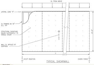
In structural engineering, a shear wall is a vertical element of a system that is designed to resist in-plane lateral forces, typically wind and seismic loads. In many jurisdictions, the International Building Code and International Residential Code govern the design of shear walls.

Concrete slab

A concrete slab is a common structural element of modern buildings, consisting of a flat, horizontal surface made of cast concrete. Steel-reinforced slabs, typically between 100 and 500 mm thick, are most often used to construct floors and ceilings, while thinner mud slabs may be used for exterior paving (see below).

Delamination Mode of failure for which a material fractures into layers

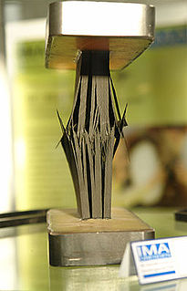
Delamination is a mode of failure where a material fractures into layers. A variety of materials including laminate composites and concrete can fail by delamination. Processing can create layers in materials such as steel formed by rolling and plastics and metals from 3D printing which can fail from layer separation. Also, surface coatings such as paints and films can delaminate from the coated substrate.

Formwork

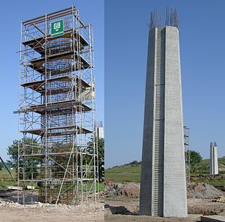
Formwork is temporary or permanent molds into which concrete or similar materials are poured. In the context of concrete construction, the falsework supports the shuttering molds.

Expansion joint

An expansion joint joint is an assembly designed to hold parts together while safely absorbing temperature-induced expansion and contraction of building materials, and vibration, or to allow movement due to ground settlement or seismic activity. They are commonly found between sections of buildings, bridges, sidewalks, railway tracks, piping systems, ships, and other structures.

This is an alphabetical list of articles pertaining specifically to structural engineering. For a broad overview of engineering, please see List of engineering topics. For biographies please see List of engineers.

Glass fiber reinforced concrete (GFRC) is a type of fiber-reinforced concrete. The product is also known as glassfibre reinforced concrete or GRC in British English. Glass fiber concretes are mainly used in exterior building façade panels and as architectural precast concrete. Somewhat similar materials are fiber cement siding and cement boards.

Fiber-reinforced concrete or fibre-reinforced concrete (FRC) is concrete containing fibrous material which increases its structural integrity. It contains short discrete fibers that are uniformly distributed and randomly oriented. Fibers include steel fibers, glass fibers, synthetic fibers and natural fibers – each of which lend varying properties to the concrete. In addition, the character of fiber-reinforced concrete changes with varying concretes, fiber materials, geometries, distribution, orientation, and densities.

Structural elements are used in structural analysis to split a complex structure into simple elements. Within a structure, an element cannot be broken down (decomposed) into parts of different kinds.

Voided biaxial slab

Voided biaxial slabs, sometimes called biaxial slabs or voided slabs, are a type of reinforced concrete slab which incorporates air-filled voids to reduce the volume of concrete required. These voids enable cheaper construction and less environmental impact. Another major benefit of the system is its reduction in slab weight compared with regular solid decks. Up to 50% of the slab volume may be removed in voids, resulting in less load on structural members. This also allows increased weight and/or span, since the self-weight of the slab contributes less to the overall load.

T-beam

A T-beam, used in construction, is a load-bearing structure of reinforced concrete, wood or metal, with a T-shaped cross section. The top of the T-shaped cross section serves as a flange or compression member in resisting compressive stresses. The web of the beam below the compression flange serves to resist shear stress and to provide greater separation for the coupled forces of bending.

The Filigree Wideslab method is a process for construction of concrete floor decks from two interconnected concrete placements, one precast in a factory, and the other done in the field. The method was developed during the late 1960s by Harry H. Wise as a more efficient and economic construction process than conventional cast-in-place technologies.

Concrete has relatively high compressive strength, but significantly lower tensile strength. The compressive strength is typically controlled with the ratio of water to cement when forming the concrete, and tensile strength is increased by additives, typically steel, to create reinforced concrete. In other words we can say concrete is made up of sand, ballast, cement and water.

Mete Avni Sözen was Kettelhut Distinguished Professor of Structural Engineering at Purdue University, Indiana, United States from 1992 to 2018.

Rigid-frame bridge Type of bridge

A Rigid-frame bridge is a bridge in which the superstructure and substructure are rigidly connected to act as a continuous unit. Typically, the structure is cast monolithically, making the structure continuous from deck to foundation. The connections between members are rigid connections which transfer bending moment, axial forces, and shear forces. A bridge design consisting of a rigid frame can provide significant structural benefits, but can also be difficult to design and/or construct.

This glossary of structural engineering terms pertains specifically to structural engineering and its sub-disciplines. Please see glossary of engineering for a broad overview of the major concepts of engineering.

References

  1. Westergaard, H.M. and Slater, W.A., ' Moments and stresses in slabs', Proceedings of the American Concrete Institute, 1921, Vol. 17, pp 415–538.
  2. Ockleston, A.J., 'Load tests on a three-storey building in Johannesburg', The Structural Engineer, 1955, Vol. 33, October, pp 304–322.
  3. Ockleston, A.J., 'Arching action in reinforced concrete slabs', The Structural Engineer, 1958, Vol. 36, No.6, pp 197–201.
  4. Johansen, K.W., 'Brudlinieteorier', Jul. Gjellerups Forlag, Copenhagen, 1943, 191pp (Yieldline theory', translated by Cement & Concrete Association, London, 1962).
  5. Wood, R.H., 'Plastic and elastic design of slabs and plates', Thames and Hudson, London, 1961.
  6. Christiansen, K.P., 'The effect of membrane stresses on the ultimate strength of an interior panel in a reinforced concrete slab', The Structural Engineer, 1963, Vol. 41, No. 8, pp 261–265.
  7. Leibenberg, A.C., 'Arch action in concrete slabs', National Building Research Institute Bulletin, 1966, No. 40. CSIR Research Report No. 234, Pretoria, S. Africa.
  8. Park, R., 'Ultimate strength of rectangular concrete slabs under short-term uniform loading with edges restrained against lateral movement', Proceedings Instn. Civ. Engrs, Vol.28, June 1964, pp. 125–150.
  9. Park, R. and Gamble, W.L., 'Reinforced concrete slabs', Wiley Interscience, New York, 1980, pp 562–612.
  10. American Concrete Institute, 'Cracking, deflection and ultimate load of concrete slab systems', SP-30, Detroit, 1971, 382 pp.
  11. Braestrup, M.W., 'Dome effect in reinforced concrete slabs: rigid-plastic analysis’, J. Struct. Div., Proc Am. Soc. Civ. Engrs, 1980, Vol 106, No. ST6, pp 1237–1253.
  12. Braestrup, M.W. and Morley, C.T., ‘Dome effect in reinforced concrete slabs: elastic-plastic analysis’, J. Struct. Div., Proc Am. Soc. Civ. Engrs, 1980, Vol 106, No. ST6, pp 1255–1262.
  13. Lahlouh, E.H. and Waldron, P., ‘Membrane action in one-way slab strips’, Proc. Instn. Civ. Engrs, Structs & Bldgs, 1992, Vol 94, Nov., pp 419–428.
  14. Kuang, J. S. and Morley, C. T., ‘A plasticity model for the punching shear of laterally restrained concrete slabs with compressive membrane action’, International Journal of Science, Vol. 35, No. 5, 1993, pp 371–385.
  15. 1 2 3 Kirkpatrick, J., Rankin, G.I.B. and Long, A.E., 'Strength evaluation of M-beam bridge deck slabs', The Structural Engineer, Vol. 62B, No 3, Sept 1984, pp 60–68.
  16. Kirkpatrick, J., Rankin, G.I.B. and Long, A.E., 'The influence of compressive membrane action on the serviceability of beam and slab bridge decks', The Structural Engineer, Vol. 64B, No 1, March 1986, pp 6–9 and 12.
  17. Department of the Environment, Northern Ireland, 'Design of M-beam bridge decks', Amendment No. 3 to the Bridge Design Code, Northern Ireland Roads Service Headquarters, March 1986, 11.1–11.5.
  18. 1 2 United Kingdom Highways Agency, 'Use of compressive membrane action in bridge decks', Design Manual for Roads and Bridges, Vol. 3, Section 4, Part 20, BD 81/02, 2002.
  19. 1 2 Kirkpatrick, J., 'An analytical field and model study of M-beam bridge decks', PhD Thesis, Dept of Civil Engineering, Queen's University of Belfast, 1982, 330 pp.
  20. Long, A.E., 'A two-phase approach to the prediction of the punching strength of slabs', Journal of the American Concrete Institute, Proceedings, Vol.72, No.2, February 1975, pp 37–45.
  21. 1 2 3 Rankin, G.I.B., 'Punching failure and compressive membrane action in reinforced concrete slabs', PhD Thesis, Dept of Civil Engineering, Queen's University of Belfast, 1982, 334 pp.
  22. McDowell. E.L., McKee, K.E. and Sevin. E. 'Arching action theory of masonry walls', Journal of the Structural Division, Proceedings, American Society of Civil Engineers, 1956, 82, No. ST2, 915-1–915-18.
  23. Hognestad, E, Hanson, N.W. and McHenry, D., 'Concrete stress distribution in ultimate strength design', Journal of the American Concrete Institute, Proceedings, Vol.52, No.6, December 1955, pp 455–479.
  24. Rankin, G.I.B. and Long, A.E. (1997), ‘Arching action strength enhancement in laterally restrained slab strips’, Proc. Instn. Civ. Engrs Structs & Bldgs, 122, Nov., pp 461–467.
  25. Long, A.E. and Rankin, G.I.B., ‘Real strength and robustness of reinforced concrete structures’, Proceedings of conference on Conservation of Engineering Structures, Institution of Civil Engineers/Royal Institute of British Architects, 1989, pp 47–58.
  26. Niblock, R., 'Compressive membrane action and the ultimate capacity of uniformly loaded reinforced concrete slabs, PhD thesis, The Queen's University of Belfast, 1986.
  27. Rankin, G.I.B., Niblock, R.A., Skates, A.S. and Long, A.E., 'Compressive membrane action strength enhancement in uniformly loaded, laterally restrained slabs', The Structural Engineer, Vol 69, No. 16, 20 August 1991, pp 287–295.
  28. Skates, A.S., Development of a design method for restrained concrete slab systems subject to concentrated and uniform loading, PhD thesis, The Queen's University of Belfast, 1987.
  29. Ruddle, M.E., 'Arching action and the ultimate capacity of reinforced concrete beams', PhD thesis, The Queen's University of Belfast, February 1989.
  30. Ruddle M.E., Rankin G.I.B. and Long A.E., 'Arching action–flexural and shear strength enhancements in rectangular and Tee beams', Proceedings of the Institution of Civil Engineers, Structures and Buildings Journal, 156, Issue 1, February 2003, pp 63–74.
  31. Peel-Cross, R.J., Rankin, G.I.B., Gilbert, S.G. and Long, A.E., ' Compressive membrane action in composite floor slabs in the Cardington LBTF', Proceedings of the Institution of Civil Engineers, Structures and Buildings Journal, 146, Issue 2, May 2001, pp 217–226.
  32. Taylor, S.E., 'Compressive membrane action in high strength concrete bridge deck slabs', PhD thesis, The Queen's University of Belfast, January 2000.
  33. Taylor, S.E., Rankin, G.I.B. and Cleland, D.J., (2001) 'Arching action in high strength concrete slabs', Proceedings of the Institution of Civil Engineers, Structures and Buildings, Vol.146, Issue 4, Nov.2001 pp 353–362
  34. Taylor, S.E., Rankin, B., Cleland, D.J, and Kirkpatrick, J., 'Serviceability of bridge deck slabs with arching action', American Concrete Institute Structural Journal, Vol. 104, No.1 January–February 2007, pp 39–48.
  35. Shaat, A.J.S., 'The real strength of laterally restrained reinforced concrete slabs, PhD thesis, Queen's University of Belfast, 2005.
  36. Taylor, S.E., Rankin, G.I.B. and Cleland, D.J., 'Guide to compressive membrane action in concrete bridge decks', Technical Paper 3, Concrete Bridge Development Group, Camberley, Surrey, 2002, 46 pp.
  37. 1 2 Hewitt , B.E. and Batchelor, B. de V., 'Punching shear strength of restrained slabs', J. Struct. Div., Proc. ASCE, Vol. 101, No. ST9, September 1975, pp 1837–1853.
  38. Batchelor, B. de V. and Tissington, I.R., 'Shear strength of two-way bridge slabs', J. Struct. Div., Proc. ASCE, Vol. 102, No. ST12, December 1976, pp 2315–2331.
  39. Ontario Ministry of Transportation and Communication, 'The Ontario highway bridge design code', 1979, Toronto, Ontario, Canada.
  40. Mufti, A. A., Jaeger, L. G., Bakht, B. and Wegner, L.D., 'Experimental investigation of fibre reinforced concrete deck slabs without internal steel reinforcement,' Canadian Journal of Civil Engineering, 1993, Vol. 20, No.3, pp 398–406.
  41. Mufti, A. A. and Newhook, J.P., 'Punching shear strength of restrained bridge deck slabs', ACI Structures Journal, 1998, 8(3), pp 375–381.