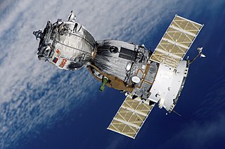
Astrionics

Last updated

Astrionics is the science and technology of the development and application of electronic systems, subsystems, and components used in spacecraft. The electronic systems on-board a spacecraft are embedded systems and include attitude determination and control, communications, command and telemetry, and computer systems. Sensors refers to the electronic components on board a spacecraft.

Contents

For engineers one of the most important considerations that must be made in the design process is the environment in which the spacecraft systems and components must operate and endure. The challenges of designing systems and components for the space environment include more than the fact that space is a vacuum.

Attitude determination and control

Overview

One of the most vital roles electronics and sensors play in a mission and performance of a spacecraft is to determine and control its attitude, or how it is oriented in space. The orientation of a spacecraft varies depending on the mission. The spacecraft may need to be stationary and always pointed at Earth, which is the case for a weather or communication satellite. However, there may also be the need to fix the spacecraft about an axis and then have it spin. The attitude determination and control system, ACS, ensures the spacecraft is behaving correctly. Below are several ways in which ACS can obtain the necessary measurements to determine this.

Magnetometer

Magnetometers measure the strength of the Earth's magnetic field in one direction. For measurements on all three axes, the required device would consist of three orthogonal magnetometers. Given the spacecraft's position, the magnetic field measurements can be compared to a known magnetic field which is given by the International Geomagnetic Reference Field model. Measurements made by magnetometers are affected by noise consisting of alignment error, scale factor errors, and spacecraft electrical activity. For near-Earth orbits, the error in the modelled field direction may vary from 0.5 degrees near the Equator to 3 degrees near the magnetic poles, where erratic auroral currents play a large role. [1] :258 The limitation of such a device is that in orbits far from Earth, the magnetic field is too weak and is actually dominated by the interplanetary field which is complicated and unpredictable.

Sun sensors

A Sun sensor works on the light entering a thin slit on top of a rectangular chamber that casts an image of a thin line on the bottom of the chamber, which is lined with a network of light-sensitive cells. These cells measure the distance of the image from a centerline and using the height of the chamber can determine the angle of refraction. The cells operate based on the photoelectric effect. Incoming photons excite electrons and therefore causing a voltage across the cell, which is, in turn, converted into a digital signal. By placing two sensors perpendicular to each other the complete direction of the Sun with respect to the sensor axes can be measured.

Digital solar aspect detectors

Also known as DSADs, these devices are purely digital Sun sensors. They determine the angles of the Sun by determining which of the light-sensitive cells in the sensor is the most strongly illuminated. By knowing the intensity of light striking neighbouring pixels, the direction of the centroid of the Sun can be calculated to within a few arcseconds. [1] :261

Earth horizon sensor

Static

Static Earth horizon sensors contain a number of sensors and sense infrared radiation from the Earth’s surface with a field of view slightly larger than the Earth. The accuracy of determining the geocenter is 0.1 degrees in near-Earth orbit to 0.01 degrees at GEO. Their use is generally restricted to spacecraft with a circular orbit. [1] :262

Scanning

Scanning Earth horizon sensors use a spinning mirror or prism and focus a narrow beam of light onto a sensing element usually called a bolometer. The spinning causes the device to sweep out the area of a cone and electronics inside the sensor detect when the infrared signal from Earth is first received and then lost. The time between is used to determine Earth’s width. From this, the roll angle can be determined. A factor that plays into the accuracy of such sensors is the fact the Earth is not perfectly circular. Another is that the sensor does not detect land or ocean, but infrared in the atmosphere which can reach certain intensities due to the season and latitude.

GPS

This sensor is simple in that using one signal many characteristics can be determined. A signal carries satellite identification, position, the duration of the propagated signal and clock information. [2] Using a constellation of 36 GPS satellites, of which only four are needed, navigation, positioning, precise time, orbit, and attitude can be determined. One advantage of GPS is all orbits from Low Earth orbit to Geosynchronous orbit can use GPS for ACS.

Command and telemetry

Overview

Another system which is vital to a spacecraft is the command and telemetry system, so much in fact, that it is the first system to be redundant. The communication from the ground to the spacecraft is the responsibility of the command system. The telemetry system handles communications from the spacecraft to the ground. Signals from ground stations are sent to command the spacecraft what to do, while telemetry reports back on the status of those commands including spacecraft vitals and mission specific data.

Command systems

The purpose of a command system is to give the spacecraft a set of instructions to perform. Commands for a spacecraft are executed based on priority. Some commands require immediate execution; other may specify particular delay times that must elapse prior to their execution, an absolute time at which the command must be executed, or an event or combination of events that must occur before the command is executed. [1] :600 Spacecraft perform a range of functions based on the command they receive. These include: power to be applied to or removed from a spacecraft subsystem or experiment, alter operating modes of the subsystem, and control various functions of the spacecraft guidance and ACS. Commands also control booms, antennas, solar cell arrays, and protective covers. A command system may also be used to upload entire programs into the RAM of programmable, micro-processor based, onboard subsystems. [1] :601

The radio-frequency signal that is transmitted from the ground is received by the command receiver and is amplified and demodulated. Amplification is necessary because the signal is very weak after traveling the long distance. Next in the command system is the command decoder. This device examines the subcarrier signal and detects the command message that it is carrying. The output for the decoder is normally non-return-to-zero data. The command decoder also provides clock information to the command logic and this tells the command logic when a bit is valid on the serial data line. The command bit stream that is sent to the command processor has a unique feature for spacecraft. Among the different types of bits sent, the first are spacecraft address bits. These carry a specific identification code for a particular spacecraft and prevent the intended command from being performed by another spacecraft. This is necessary because there are many satellites using the same frequency and modulation type. [1] :606

The microprocessor receives inputs from the command decoder, operates on these inputs in accordance with a program that is stored in ROM or RAM, and then outputs the results to the interface circuitry. Because there is such a wide variety of command types and messages, most command systems are implemented using programmable micro-processors. The type of interface circuitry needed is based on the command sent by the processor. These commands include relay, pulse, level, and data commands. Relay commands activate the coils of electromagnetic relays in the central power switching unit. Pulse commands are short pulses of voltage or current that is sent by the command logic to the appropriate subsystem. A level command is exactly like a logic pulse command except that a logic level is delivered instead of a logic pulse. Data commands transfer data words to the destination subsystem. [1] :612–615

Telemetry systems

Commands to a spacecraft would be useless if ground control did not know what the spacecraft was doing. Telemetry includes information such as:

The telemetry system is responsible for acquisition from the sensors, conditioners, selectors, and converters, for processing, including compression, format, and storage, and finally for transmission, which includes encoding, modulating, transmitting and the antenna.

There are several unique features of telemetry system design for spacecraft. One of these is the approach to the fact that for any given satellite in LEO, because it is traveling so quickly, it may only be in contact with a particular station for ten to twenty minutes. This would require hundreds of ground stations to stay in constant communication, which is not at all practical. One solution to this is onboard data storage. Data storage can accumulate data slowly throughout the orbit and dump it quickly when over a ground station. In deep space missions, the recorder is often used the opposite way, to capture high-rate data and play it back slowly over data-rate-limited links. [1] :567 Another solution is data relay satellites. NASA has satellites in GEO called TDRS, Tracking and Data Relay Satellites, which relay commands and telemetry from LEO satellites. Prior to TDRS, astronauts could communicate with the Earth for only about 15% of the orbit, using 14 NASA ground stations around the world. With TDRS, coverage of low-altitude satellites is global, from a single ground station at White Sands, New Mexico. [1] :569

Another unique feature of telemetry systems is autonomy. Spacecraft require the ability to monitor their internal functions and act on information without ground control interaction. The need for autonomy originates from problems such as insufficient ground coverage, communication geometry, being too near the Earth-Sun line (where solar noise interferes with radio frequencies), or simply for security purposes. Autonomy is important so that the telemetry system already has the capability to monitor the spacecraft functions and the command systems have the ability to give the necessary commands to reconfigure based on the needs of the action to be taken. There are three steps to this process:

1. The telemetry system must be able to recognize when one of the functions it's monitoring deviates beyond the normal ranges.

2. The command system must know how to interpret abnormal functions, so that it can generate a proper command response.

3. The command and telemetry systems must be capable of communicating with each other. [1] :623

Sensors

Sensors can be classified into two categories: health sensors and payload sensors. Health sensors monitor the spacecraft or payload functionality and can include temperature sensors, strain gauges, gyros and accelerometers. Payload sensors may include radar imaging systems and IR cameras. While payload sensors represent some of the reason the mission exists, it is the health sensors that measure and control systems to ensure optimum operation.

See also

Related Research Articles

<span class="mw-page-title-main">Pioneer 0</span> 1958 failed U.S. space probe

Pioneer 0 was a failed United States space probe that was designed to go into orbit around the Moon, carrying a television camera, a micrometeorite detector and a magnetometer. It was part of the first International Geophysical Year (IGY) science payload. It was designed and operated by the Air Force Ballistic Missile Division as the first spacecraft in the Pioneer program and was the first attempted launch beyond Earth orbit by any country, but the rocket failed shortly after launch. The probe was intended to be called Pioneer, but the launch failure precluded that name.

<span class="mw-page-title-main">Vanguard 3</span>

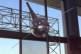
Vanguard 3 is a scientific satellite that was launched into Earth orbit by the Vanguard SLV-7 on 18 September 1959, the third successful Vanguard launch out of eleven attempts. Vanguard rocket: Vanguard Satellite Launch Vehicle-7 (SLV-7) was an unused Vanguard TV-4BU rocket, updated to the final production Satellite Launch Vehicle (SLV).

<span class="mw-page-title-main">Explorer 6</span> NASA satellite of the Explorer program

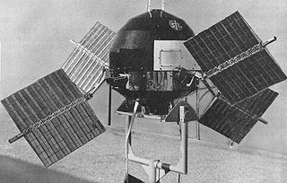
Explorer 6, or S-2, was a NASA satellite, launched on 7 August 1959, at 14:24:20 GMT. It was a small, spheroidal satellite designed to study trapped radiation of various energies, galactic cosmic rays, geomagnetism, radio propagation in the upper atmosphere, and the flux of micrometeorites. It also tested a scanning device designed for photographing the Earth's cloud cover. On 14 August 1959, Explorer 6 took the first photos of Earth from a satellite.

<span class="mw-page-title-main">IMAGE (spacecraft)</span> NASA satellite of the Explorer program

IMAGE is a NASA Medium Explorer mission that studied the global response of the Earth's magnetosphere to changes in the solar wind. It was believed lost but as of August 2018 might be recoverable. It was launched 25 March 2000, at 20:34:43.929 UTC, by a Delta II launch vehicle from Vandenberg Air Force Base on a two-year mission. Almost six years later, it unexpectedly ceased operations in December 2005 during its extended mission and was declared lost. The spacecraft was part of NASA's Sun-Earth Connections Program, and its data has been used in over 400 research articles published in peer-reviewed journals. It had special cameras that provided various breakthroughs in understanding the dynamics of plasma around the Earth. The principal investigator was Jim Burch of the Southwest Research Institute.

The design of spacecraft covers a broad area, including the design of both robotic spacecraft, and spacecraft for human spaceflight.

The on-board data handling (OBDH) subsystem of a spacecraft is the subsystem which carries and stores data between the various electronics units and the ground segment, via the telemetry, tracking and command (TT&C) subsystem.

The Canadian Advanced Nanospace eXperiment (CanX) program is a Canadian CubeSat nanosatellite program operated by the University of Toronto Institute for Aerospace Studies, Space Flight Laboratory (UTIAS/SFL). The program's objectives are to involve graduate students in the process of spaceflight development, and to provide low-cost access to space for scientific research and the testing of nanoscale devices. The CanX projects include CanX-1, CanX-2, the BRIght Target Explorer (BRITE), and CanX-4&5.
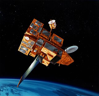
<span class="mw-page-title-main">Explorer 61</span> NASA satellite of the Explorer program

Magsat was a NASA/USGS spacecraft, launched on 30 October 1979. The mission was to map the Earth's magnetic field, the satellite had two magnetometers. The scalar and vector magnetometers gave Magsat a capability beyond that of any previous spacecraft. Extended by a telescoping boom, the magnetometers were distanced from the magnetic field created by the satellite and its electronics. The satellite carried two magnetometers, a three-axis fluxgate magnetometer for determining the strength and direction of magnetic fields, and an ion-vapor/vector magnetometer for determining the magnetic field caused by the vector magnetometer itself. Magsat is considered to be one of the more important Science/Earth orbiting satellites launched; the data it accumulated is still being used, particularly in linking new satellite data to past observations.

<span class="mw-page-title-main">FASTRAC</span>

Formation Autonomy Spacecraft with Thrust, Relnav, Attitude and Crosslink is a pair of nanosatellites developed and built by students at The University of Texas at Austin. The project is part of a program sponsored by the Air Force Research Laboratory (AFRL), whose goal is to lead the development of affordable space technology. The FASTRAC mission will specifically investigate technologies that facilitate the operation of multiple satellites in formation. These enabling technologies include relative navigation, cross-link communications, attitude determination, and thrust. Due to the high cost of lifting mass into orbit, there is a strong initiative to miniaturize the overall weight of spacecraft. The utilization of formations of satellites, in place of large single satellites, reduces the risk of single point failure and allows for the use of low-cost hardware.

<span class="mw-page-title-main">Orbiting Vehicle</span> American satellite family

Orbiting Vehicle or OV, originally designated SATAR, comprised five disparate series of standardized American satellites operated by the US Air Force, launched between 1965 and 1971. Forty seven satellites were built, of which forty three were launched and thirty seven reached orbit. With the exception of the OV3 series and OV4-3, they were launched as secondary payloads, using excess space on other missions. This resulted in extremely low launch costs and short proposal-to-orbit times. Typically, OV satellites carried scientific and/or technological experiments, 184 being successfully orbited through the lifespan of the program.

SSETI Express was the first spacecraft to be designed and built by European students and was launched by the European Space Agency. SSETI Express is a small spacecraft, similar in size and shape to a washing machine. On board the student-built spacecraft were three CubeSat picosatellites, extremely small satellites weighing around one kg each. These were deployed one hour and forty minutes after launch. Twenty-one university groups, working from locations spread across Europe and with very different cultural backgrounds, worked together via the internet to jointly create the satellite. The expected lifetime of the mission was planned to be 2 months. SSETI Express encountered an unusually fast mission development: less than 18 months from kick-off in January 2004 to flight-readiness.

<span class="mw-page-title-main">Radio Aurora Explorer</span>

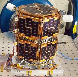
Radio Aurora Explorer (RAX) is the first National Science Foundation sponsored CubeSat mission. The RAX mission is a joint effort between SRI International in Menlo Park, California and the University of Michigan in Ann Arbor, Michigan. The chief scientist at SRI International, Dr. Hasan Bahcivan, led his team at SRI to develop the payload while the chief engineer, Dr. James Cutler, led a team of students to develop the satellite bus in the Michigan Exploration Laboratory. There are currently two satellites in the RAX mission.

<span class="mw-page-title-main">ADEOS II</span> Japanese Earth observation satellite

ADEOS II was an Earth observation satellite (EOS) launched by NASDA, with contributions from NASA and CNES, in December 2002. and it was the successor to the 1996 mission ADEOS I. The mission ended in October 2003 after the satellite's solar panels failed.

Spacecraft attitude control is the process of controlling the orientation of a spacecraft with respect to an inertial frame of reference or another entity such as the celestial sphere, certain fields, and nearby objects, etc.

<span class="mw-page-title-main">Explorer 10</span> NASA satellite of the Explorer program

Explorer 10 was a NASA satellite that investigated Earth's magnetic field and nearby plasma. Launched on 25 March 1961, it was an early mission in the Explorer program and was the first satellite to measure the "shock wave" generated by a solar flare.

<span class="mw-page-title-main">Ground segment</span> Ground-based elements of a spacecraft system

A ground segment consists of all the ground-based elements of a space system used by operators and support personnel, as opposed to the space segment and user segment. The ground segment enables management of a spacecraft, and distribution of payload data and telemetry among interested parties on the ground. The primary elements of a ground segment are:

Explorer 36 was a NASA satellite launched as part of the Explorer program, being the second of the two satellites GEOS. Explorer 36 was launched on 11 January 1968 from Vandenberg Air Force Base, with Thor-Delta E1 launch vehicle.

<span class="mw-page-title-main">Nanosat 01</span>

The Nanosat 01, sometimes written as NanoSat-1 or NanoSat 01, was an artificial satellite developed by the Spanish Instituto Nacional de Técnica Aeroespacial (INTA) and launched the 18th of December 2004. Considered a nano satellite for its weight of less than 20 kg, its main mission was forwarding communications between far reaching points of the Earth such as Juan Carlos I Antarctic Base from mainland Spain. This was possible due to its polar orbit and altitude of 650 km above sea level. During an operational run the data obtained in the Antarctic would be uploaded to the satellite during its fly by and then, downloaded in Spain when satellite reached the Iberian Peninsula.

<span class="mw-page-title-main">OPTOS</span> Spanish nanosatellite

OPTOS was a Spanish nanosatellite designed and developed by INTA with support from the European Cooperation for Space Standardization (ECSS) as a low-cost technology demonstrator. It was launched in 2013 and had a service life of three years.

<i>Galileo</i> (spacecraft) NASA probe sent to Jupiter (1989–2003)

Galileo was an American robotic space probe that studied the planet Jupiter and its moons, as well as the asteroids Gaspra and Ida. Named after the Italian astronomer Galileo Galilei, it consisted of an orbiter and an entry probe. It was delivered into Earth orbit on October 18, 1989, by Space ShuttleAtlantis , during STS-34. Galileo arrived at Jupiter on December 7, 1995, after gravitational assist flybys of Venus and Earth, and became the first spacecraft to orbit an outer planet.

References

  1. 1 2 3 4 5 6 7 8 9 10 11 Pisacane, Vincent L. Fundamentals of Space Systems. New York, Oxford University Press, 2005
  2. Abid, Mohamed M. Spacecraft Sensors. West Sussex, John Wiley and Sons Ltd., 2005, p301