Balanced audio

Last updated

Balanced audio is a method of interconnecting audio equipment using balanced interfaces. This type of connection is very important in sound recording and production because it allows the use of long cables while reducing susceptibility to external noise caused by electromagnetic interference. The balanced interface guarantees that induced noise appears as common-mode voltages at the receiver which can be rejected by a differential device.

Contents

Balanced connections typically use shielded twisted-pair cable and three-conductor connectors. The connectors are usually three-pin XLR or 14 inch (6.35 mm) TRS phone connectors. When used in this manner, each cable carries one channel, therefore stereo audio (for example) would require two of them.

A common misconception is that balanced audio requires the signal source to deliver equal waveforms of opposite polarity to the two signal conductors of the balanced line. However, many balanced devices actively drive only one side of the line, but do so at an impedance that is equal to the impedance of the non-driven side of the line. This impedance balance permits the balanced line receiver (input stage of the next device) to reject common-mode signals introduced to the two conductors by electromagnetic coupling.

Applications

Many microphones operate at low voltage levels and some with high output impedance (hi-Z), which makes long microphone cables especially susceptible to electromagnetic interference. Microphone interconnections are therefore a common application for a balanced interconnection, which allows the receiver to reject most of this induced noise. If the power amplifiers of a public address system are located at any distance from the mixing console, it is also normal to use balanced lines for the signal paths from the mixer to these amplifiers. Many other components, such as graphic equalizers and effects units, have balanced inputs and outputs to allow this. In recording and for short cable runs in general, a compromise is necessary between the noise reduction given by balanced lines and the cost introduced by the extra circuitry they require.

Some devices, usually with a transformer output, provide a balanced output that is "floating" with respect to ground; the impedance to ground from each side of the output is high. More commonly, devices drive one or both sides of the balanced interface with a signal referenced to ground. When one side is not driven, care is taken to assure that the impedance to ground is equal to the impedance of the driven side.

Interference reduction

Balanced audio connections use a number of techniques to reduce noise.

A typical balanced cable contains two identical wires, which are twisted together and then wrapped with a third conductor (foil or braid) that acts as a shield. The two wires form a circuit that can carry an audio signal.

The term balanced comes from the method of balancing the impedance of each wire in the circuit; the line and all circuits directly connected to it (such as the driver and receiver) must have identical impedances with respect to some reference point. This means that much of the electromagnetic interference will induce an equal noise voltage in each wire. Since the differential device at the receiving end only responds to the difference in voltage between the two signal lines, noise that is identical on both wires is rejected. This method can be implemented with a differential amplifier. A transformer may also be used instead of an active input stage.

A twisted pair makes the loop area between the conductors as small as possible, and ensures that a magnetic field that passes equally through adjacent loops will induce equal levels of noise on both lines, which is canceled out by the differential device in the receiver. If the noise source is extremely close to the cable, then it is possible it will be induced on one of the lines more than the other, and it will not be canceled as well, but canceling will still occur to the extent of the amount of noise that is equal on both lines.

The separate shield that’s commonly provided in a balanced audio cable also yields a noise rejection advantage over an unbalanced two-conductor arrangement (such as used in typical home stereos) where the shield must also act as the signal return wire. Therefore, any noise currents induced into a balanced audio shield will not be directly modulated onto the signal, whereas in a two-conductor system they will be. This also prevents ground loop problems, by separating the shield/chassis from signal ground.

Differential signaling

Signals are often transmitted over balanced connections using the differential mode, meaning the wires carry signals that are equal in magnitude but of opposite polarity to each other (for instance, in an XLR connector, pin 2 carries the signal with normal polarity, and pin 3 carries an inverted version of the same signal). Despite popular belief, this arrangement is not necessary for noise rejection. As long as the impedances are balanced, noise will couple equally into the two wires (and be rejected by a differential amplifier), regardless of the signal that is present on them. [1] [2] A simple method of driving a balanced line is to inject the signal into the "hot" wire through a known source impedance, and connect the "cold" wire to the signal's local ground reference through an identical impedance. Due to common misconceptions about differential signalling, this is often referred to as a quasi-balanced or impedance-balanced output, though it is, in fact, fully balanced and will reject common-mode interference.

However, there are some minor benefits to driving the line with a fully differential output:

Internally balanced audio design

Professional audio products (recording, public address, etc.) generally provide balanced inputs and outputs, typically via XLR or TRS phone connectors. However, in most cases, the internal circuitry is entirely unbalanced.

A small number of audio products have been designed with an entirely balanced signal path from input to output; the circuitry maintains its impedance balance throughout the device. This design is achieved by providing identical (mirrored) internal signal paths for both the "hot" and "cold" conductors. In critical applications, a 100% balanced circuit design can offer better signal integrity by avoiding the extra amplifier stages or transformers required for front-end unbalancing and back-end rebalancing. [3]

Connectors

Three-pin XLR connectors and quarter-inch (¼" or 6.35 mm) TRS phone connectors are commonly used for balanced audio interfaces. Many jacks are now designed to take either XLR or TRS phone plugs. Equipment intended for long-term installation sometimes uses terminal strips or Euroblock connectors. Some balanced headphone connections also use a Pentaconn 4.4 mm TRRRS connector.

With XLR connectors, pins 1, 2, and 3 are usually used for the shield (ideally connected to the chassis) and the two signal wires, respectively. (The phrase "ground, live, return", corresponding to "X, L, R", is often offered as a memory aid, although the second signal wire is not a "return" in the case of differential signaling) On TRS phone plugs, the tip is signal/non-inverting, the ring is return/inverting, and the sleeve is chassis ground.

If a stereophonic or other binaural signal is plugged into such a jack, one channel (usually the right) will be subtracted from the other (usually the left), leaving an unlistenable L − R (left minus right) signal instead of normal monophonic L + R (left plus right). Reversing the polarity at any other point in a balanced audio system will also result in this effect at some point when it is later mixed-down with its other channel.

Telephone lines also carry audio through balanced circuitry, though this is generally now limited to the local loop. It is called this because the two wires form a balanced loop through which both sides of the telephone call travel. As telephones require DC power to operate and to allow simple on/off hook detection, extra circuitry was developed where one signal wire is fed from the exchange power bus, typically 50 volts, and the other grounded, both via equal value inductors which have about 400 ohms DC resistance, to avoid short-circuiting the wanted AC signal and to maintain impedance balance.

Digital audio connections in professional environments are also frequently balanced, normally following the AES3 (AES/EBU) standard. This uses XLR connectors and twisted-pair cable with 110-ohm impedance. By contrast, the coaxial S/PDIF interface commonly seen on consumer equipment is unbalanced.

Converters

Balanced and unbalanced circuits can be interfaced by the use of a balun, often through a DI unit (also called a "DI box" or "direct box").

As a last resort a balanced audio line can be fed into an unbalanced input and vice versa as long as the electronic design used for the output stage is known. In the case of balanced output to unbalanced input, the negative output can be tied to ground, but in certain cases the negative output should be left disconnected. [4]

See also

Related Research Articles

In telecommunications and professional audio, a balanced line or balanced signal pair is an electrical circuit consisting of two conductors of the same type, both of which have equal impedances along their lengths, to ground, and to other circuits. The primary advantage of the balanced line format is good rejection of common-mode noise and interference when fed to a differential device such as a transformer or differential amplifier.
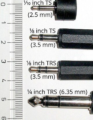
<span class="mw-page-title-main">Phone connector (audio)</span> Family of connectors typically used for analog signals

A phone connector, also known as phone jack, audio jack, headphone jack or jack plug, is a family of electrical connectors typically used for analog audio signals. A plug, the "male" connector, is inserted into the jack, the "female" connector.

<span class="mw-page-title-main">Balun</span> Electrical device

A balun is an electrical device that allows balanced and unbalanced lines to be interfaced without disturbing the impedance arrangement of either line. A balun can take many forms and may include devices that also transform impedances but need not do so. Sometimes, in the case of transformer baluns, they use magnetic coupling but need not do so. Common-mode chokes are also used as baluns and work by eliminating, rather than rejecting, common mode signals.

<span class="mw-page-title-main">XLR connector</span> Style of electrical connector found primarily in professional audio and lighting

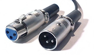
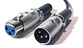
The XLR connector is a type of electrical connector primarily used in professional audio, video, and stage lighting equipment. XLR connectors are cylindrical in design, with three to seven connector pins, and are often employed for analog balanced audio interconnections, AES3 digital audio, portable intercom, DMX512 lighting control, and for low-voltage power supply. XLR connectors are included to the international standard for dimensions, IEC 61076-2-103. The XLR connector is superficially similar to the smaller DIN connector, with which it is physically incompatible.

<span class="mw-page-title-main">Phantom power</span> DC power through microphone cables

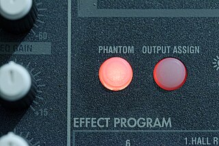
Phantom power, in the context of professional audio equipment, is DC electric power equally applied to both signal wires in balanced microphone cables, forming a phantom circuit, to operate microphones that contain active electronic circuitry. It is best known as a convenient power source for condenser microphones, though many active direct boxes also use it. The technique is also used in other applications where power supply and signal communication take place over the same wires.

<span class="mw-page-title-main">DI unit</span> Audio signal conversion device

A DI unit is an electronic device typically used in recording studios and in sound reinforcement systems to connect a high output impedance unbalanced output signal to a low-impedance, microphone level, balanced input, usually via an XLR connector and XLR cable. DIs are frequently used to connect an electric guitar or electric bass to a mixing console's microphone input jack. The DI performs level matching, balancing, and either active buffering or passive impedance matching/impedance bridging. DI units are typically metal boxes with input and output jacks and, for more expensive units, “ground lift” and attenuator switches.

Line level is the specified strength of an audio signal used to transmit analog audio between components such as CD and DVD players, television sets, audio amplifiers, and mixing consoles.

In an electrical system, a ground loop or earth loop occurs when two points of a circuit are intended to have the same ground reference potential but instead have a different potential between them. This is typically caused when enough current is flowing in the connection between the two ground points to produce a voltage drop and cause two points to be at different potentials. Current may be produced in a circular ground connection by electromagnetic induction.

<span class="mw-page-title-main">Differential signalling</span> Method for electrically transmitting information

Differential signalling is a method for electrically transmitting information using two complementary signals. The technique sends the same electrical signal as a differential pair of signals, each in its own conductor. The pair of conductors can be wires in a twisted-pair or ribbon cable or traces on a printed circuit board.

<span class="mw-page-title-main">Shielded cable</span> Electric cable with metal jacket (shield) to prevent magnetic interference

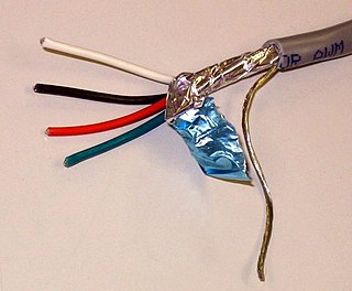
A shielded cable or screened cable is an electrical cable that has a common conductive layer around its conductors for electromagnetic shielding. This shield is usually covered by an outermost layer of the cable. Common types of cable shielding can most broadly be categorized as foil type, contraspiralling wire strands or both. A longitudinal wire may be necessary with dielectric spiral foils to short out each turn.

In audio processing and sound reinforcement, an insert is an access point built into the mixing console, allowing the audio engineer to add external line level devices into the signal flow between the microphone preamplifier and the mix bus.

A radio transmitter or receiver is connected to an antenna which emits or receives the radio waves. The antenna feed system or antenna feed is the cable or conductor, and other associated equipment, which connects the transmitter or receiver with the antenna and makes the two devices compatible. In a radio transmitter, the transmitter generates an alternating current of radio frequency, and the feed system feeds the current to the antenna, which converts the power in the current to radio waves. In a radio receiver, the incoming radio waves excite tiny alternating currents in the antenna, and the feed system delivers this current to the receiver, which processes the signal.

<span class="mw-page-title-main">Transformer types</span> Overview of electrical transformer types

A variety of types of electrical transformer are made for different purposes. Despite their design differences, the various types employ the same basic principle as discovered in 1831 by Michael Faraday, and share several key functional parts.

In electrical engineering, a balanced circuit is electronic circuitry for use with a balanced line, or the balanced line itself. Balanced lines are a common method of transmitting many types of electrical signals between two points on two wires. In a balanced line, the two signal lines are of a matched impedance to help ensure that interference, induced in the line, is common-mode and can be removed at the receiving end by circuitry with good common-mode rejection. To maintain the balance, circuit blocks which interface to the line or are connected in the line must also be balanced.

Many different electrical connectors have been used to connect microphones to audio equipment—including PA systems, radios, tape recorders, and numerous other devices.

In electrical engineering, a common-mode signal is the identical component of voltage present at both input terminals of an electrical device. In telecommunication, the common-mode signal on a transmission line is also known as longitudinal voltage.

Audio connectors and video connectors are electrical or optical connectors for carrying audio or video signals. Audio interfaces or video interfaces define physical parameters and interpretation of signals. For digital audio and digital video, this can be thought of as defining the physical layer, data link layer, and most or all of the application layer. For analog audio and analog video these functions are all represented in a single signal specification like NTSC or the direct speaker-driving signal of analog audio.

<span class="mw-page-title-main">Y-cable</span> Cable with three ends

A Y-cable, Y cable, or splitter cable is a cable with three ends: one common end and two other ends. The Y-cable can resemble the Latin letter "Y".

<span class="mw-page-title-main">Unbalanced circuit</span>

In electrical engineering, an unbalanced circuit is one in which the transmission properties between the ports of the circuit are different for the two poles of each port. It is usually taken to mean that one pole of each port is bonded to a common potential but more complex topologies are possible. This common point is commonly called ground or earth but it may well not actually be connected to electrical ground at all.

<span class="mw-page-title-main">Star quad cable</span> Type of electrical cable configuration

In electrical engineering, star-quad cable is a four-conductor electrical cable that has a special quadrupole geometry which provides magnetic immunity when used in a balanced line. Four conductors are used to carry the two legs of the balanced line. All four conductors must be an equal distance from a common point. The four conductors are arranged in a four-pointed star. Opposite points of the star are connected together at each end of the cable to form each leg of the balanced circuit.

References

  1. 1 2 3 Graham Blyth. "Audio Balancing Issues". White Papers. Soundcraft. Archived from the original on 4 December 2010. Retrieved 2010-12-30.
  2. "Part 3: Amplifiers". Sound system equipment (Third ed.). Geneva: International Electrotechnical Commission. 2000. p. 111. IEC 602689-3:2001. Only the common-mode impedance balance of the driver, line, and receiver play a role in noise or interference rejection. This noise or interference rejection property is independent of the presence of a desired differential signal.
  3. Karki, James (2016) [2002]. "Texas Instruments Application Report SLOA054E: Fully-Differential Amplifiers" (PDF). Texas Instruments. Archived from the original on 5 November 2020. Retrieved 10 June 2021.
  4. Rane technical staff. "Sound System Interconnection". ranecommercial.com. Archived from the original on 2021-07-29. Retrieved 2021-12-29.