A beam waveguide antenna is a particular type of antenna dish, at which waveguides are used to transmit the radio beam between the large steerable dish and the equipment for reception or transmission, like e.g. RF power amplifiers.
Contents

A beam waveguide antenna is a particular type of antenna dish, at which waveguides are used to transmit the radio beam between the large steerable dish and the equipment for reception or transmission, like e.g. RF power amplifiers.

Beam waveguide antennas are used in large radio telescopes and satellite communication stations as an alternative to the most common parabolic antenna design, the conventional "front fed" parabolic antenna. In front feed, the antenna feed, the small antenna that transmits or receives the radio waves reflected by the dish, is suspended at the focus, in front of the dish. However, this location causes a number of practical difficulties. In high performance systems, complex transmitter and receiver electronics must be located at the feed antenna. This feed equipment usually requires high maintenance; some examples are water cooling for transmitters and cryogenic cooling for sensitive receivers. With the large dishes used in these systems, the focus is high off the ground, and servicing requires cranes or scaffolds, and outdoor work with delicate equipment high off the ground. Furthermore, the feeds themselves have to be designed to handle outdoor conditions such as rain and large temperature swings, and to work while tipped at any angle.
The beam waveguide antenna addresses these problems by locating the feed antenna in a "feed house" at the base of the antenna, instead of in front of the dish. The radio waves collected by the dish are focused into a beam and reflected by metal surfaces in a path through the supporting structure to the stationary feed antenna at the base. The path is complicated because the beam must pass through both axes of the altazimuth mount of the antenna, so turning the antenna does not disturb the beam.

Beam waveguides, which propagate a microwave beam using a series of reflectors, were proposed as early as 1964. [2] By 1968, there were proposals to handle some of the signal path in pointable antennas by these techniques. [3] By 1970, a fully beam-waveguide approach was proposed for satellite communication antennas. [4] At first, it was believed the complicated signal path with its multiple reflecting surfaces would result in unacceptable signal loss [5] but further analysis showed the waveguide system could be built with very low losses.
The first full scale beam waveguide antenna was the 64 meter antenna at the Usuda Deep Space Center, Japan, built in 1984 by the Japan Aerospace Exploration Agency. [6] After the Jet Propulsion Lab (JPL) tested this antenna and found it better than their conventional 64-meter antennas, [7] they too switched to this method of construction for all subsequent antennas of their Deep Space Network (DSN).

Microwave is a form of electromagnetic radiation with wavelengths ranging from about 30 centimeters to one millimeter corresponding to frequencies between 1000 MHz and 300 GHz respectively. Different sources define different frequency ranges as microwaves; the above broad definition includes UHF, SHF and EHF bands. A more common definition in radio-frequency engineering is the range between 1 and 100 GHz. In all cases, microwaves include the entire SHF band at minimum. Frequencies in the microwave range are often referred to by their IEEE radar band designations: S, C, X, Ku, K, or Ka band, or by similar NATO or EU designations.

In telecommunications and radar, a Cassegrain antenna is a parabolic antenna in which the feed antenna is mounted at or behind the surface of the concave main parabolic reflector dish and is aimed at a smaller convex secondary reflector suspended in front of the primary reflector. The beam of radio waves from the feed illuminates the secondary reflector, which reflects it back to the main reflector dish, which reflects it forward again to form the desired beam. The Cassegrain design is widely used in parabolic antennas, particularly in large antennas such as those in satellite ground stations, radio telescopes, and communication satellites.

In electrical engineering, a circulator is a passive, non-reciprocal three- or four-port device that only allows a microwave or radio-frequency (RF) signal to exit through the port directly after the one it entered. Optical circulators have similar behavior. Ports are where an external waveguide or transmission line, such as a microstrip line or a coaxial cable, connects to the device. For a three-port circulator, a signal applied to port 1 only comes out of port 2; a signal applied to port 2 only comes out of port 3; a signal applied to port 3 only comes out of port 1, and so on. An ideal three-port circulator has the following scattering matrix:

A radio telescope is a specialized antenna and radio receiver used to detect radio waves from astronomical radio sources in the sky. Radio telescopes are the main observing instrument used in radio astronomy, which studies the radio frequency portion of the electromagnetic spectrum emitted by astronomical objects, just as optical telescopes are the main observing instrument used in traditional optical astronomy which studies the light wave portion of the spectrum coming from astronomical objects. Unlike optical telescopes, radio telescopes can be used in the daytime as well as at night.
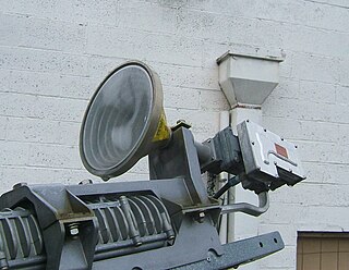
A feed horn is a small horn antenna used to couple a waveguide to e.g. a parabolic dish antenna or offset dish antenna for reception or transmission of microwave. A typical application is the use for satellite television reception with a satellite dish. In that case the feed horn can either be a separate part used together with e.g. a "low-noise block downconverter" (LNB), or more typically today is integrated into a "low-noise block feedhorn" (LNBF).
The Ku band is the portion of the electromagnetic spectrum in the microwave range of frequencies from 12 to 18 gigahertz (GHz). The symbol is short for "K-under", because it is the lower part of the original NATO K band, which was split into three bands because of the presence of the atmospheric water vapor resonance peak at 22.24 GHz, (1.35 cm) which made the center unusable for long range transmission. In radar applications, it ranges from 12 to 18 GHz according to the formal definition of radar frequency band nomenclature in IEEE Standard 521–2002.

A parabolic antenna is an antenna that uses a parabolic reflector, a curved surface with the cross-sectional shape of a parabola, to direct the radio waves. The most common form is shaped like a dish and is popularly called a dish antenna or parabolic dish. The main advantage of a parabolic antenna is that it has high directivity. It functions similarly to a searchlight or flashlight reflector to direct radio waves in a narrow beam, or receive radio waves from one particular direction only. Parabolic antennas have some of the highest gains, meaning that they can produce the narrowest beamwidths, of any antenna type. In order to achieve narrow beamwidths, the parabolic reflector must be much larger than the wavelength of the radio waves used, so parabolic antennas are used in the high frequency part of the radio spectrum, at UHF and microwave (SHF) frequencies, at which the wavelengths are small enough that conveniently-sized reflectors can be used.

The NASA Deep Space Network (DSN) is a worldwide network of American spacecraft communication ground segment facilities, located in the United States (California), Spain (Madrid), and Australia (Canberra), that supports NASA's interplanetary spacecraft missions. It also performs radio and radar astronomy observations for the exploration of the Solar System and the universe, and supports selected Earth-orbiting missions. DSN is part of the NASA Jet Propulsion Laboratory (JPL).
Super high frequency (SHF) is the ITU designation for radio frequencies (RF) in the range between 3 and 30 gigahertz (GHz). This band of frequencies is also known as the centimetre band or centimetre wave as the wavelengths range from one to ten centimetres. These frequencies fall within the microwave band, so radio waves with these frequencies are called microwaves. The small wavelength of microwaves allows them to be directed in narrow beams by aperture antennas such as parabolic dishes and horn antennas, so they are used for point-to-point communication and data links and for radar. This frequency range is used for most radar transmitters, wireless LANs, satellite communication, microwave radio relay links, satellite phones, and numerous short range terrestrial data links. They are also used for heating in industrial microwave heating, medical diathermy, microwave hyperthermy to treat cancer, and to cook food in microwave ovens.

The Goldstone Deep Space Communications Complex (GDSCC), commonly called the Goldstone Observatory, is a satellite ground station located in Fort Irwin in the U.S. state of California. Operated by NASA's Jet Propulsion Laboratory (JPL), its main purpose is to track and communicate with interplanetary space missions. It is named after Goldstone, California, a nearby gold-mining ghost town.

A horn antenna or microwave horn is an antenna that consists of a flaring metal waveguide shaped like a horn to direct radio waves in a beam. Horns are widely used as antennas at UHF and microwave frequencies, above 300 MHz. They are used as feed antennas for larger antenna structures such as parabolic antennas, as standard calibration antennas to measure the gain of other antennas, and as directive antennas for such devices as radar guns, automatic door openers, and microwave radiometers. Their advantages are moderate directivity, broad bandwidth, low losses, and simple construction and adjustment.

An orthomode transducer (OMT) is a waveguide component that is commonly referred to as a polarisation duplexer. Orthomode is a contraction of orthogonal mode. Orthomode transducers serve either to combine or to separate two orthogonally polarized microwave signal paths. One of the paths forms the uplink, which is transmitted over the same waveguide as the received signal path, or downlink path. Such a device may be part of a very small aperture terminal (VSAT) antenna feed or a terrestrial microwave radio feed; for example, OMTs are often used with a feed horn to isolate orthogonal polarizations of a signal and to transfer transmit and receive signals to different ports.

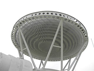
An antenna reflector is a device that reflects electromagnetic waves. Antenna reflectors can exist as a standalone device for redirecting radio frequency (RF) energy, or can be integrated as part of an antenna assembly.

An offset dish antenna or off-axis dish antenna is a type of parabolic antenna. It is so called because the antenna feed is offset to the side of the reflector, in contrast to the common "front-feed" parabolic antenna where the feed antenna is suspended in front of the dish, on its axis. As in a front-fed parabolic dish, the feed is located at the focal point of the reflector, but the reflector is an asymmetric segment of a paraboloid, so the focus is located to the side.
A radio transmitter or receiver is connected to an antenna which emits or receives the radio waves. The antenna feed system or antenna feed is the cable or conductor, and other associated equipment, which connects the transmitter or receiver with the antenna and makes the two devices compatible. In a radio transmitter, the transmitter generates an alternating current of radio frequency, and the feed system feeds the current to the antenna, which converts the power in the current to radio waves. In a radio receiver, the incoming radio waves excite tiny alternating currents in the antenna, and the feed system delivers this current to the receiver, which processes the signal.

Microwave transmission is the transmission of information by electromagnetic waves with wavelengths in the microwave frequency range of 300 MHz to 300 GHz of the electromagnetic spectrum. Microwave signals are normally limited to the line of sight, so long-distance transmission using these signals requires a series of repeaters forming a microwave relay network. It is possible to use microwave signals in over-the-horizon communications using tropospheric scatter, but such systems are expensive and generally used only in specialist roles.

A focal cloud is the collection of focal points of an imperfect lens or parabolic reflector whether optical, electrostatic or electromagnetic. This includes parabolic antennas and lens-type reflective antennas of all kinds. The effect is analogous to the circle of confusion in photography.
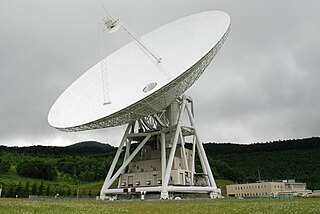
Usuda Deep Space Center is a facility of the Japan Aerospace Exploration Agency. It is a spacecraft tracking station in Saku, Nagano, opened in October, 1984. The main features of the station are two large beam waveguide antennas, an older 64 meter antenna and a newer 54 meter dish.

An antenna array is a set of multiple connected antennas which work together as a single antenna, to transmit or receive radio waves. The individual antennas are usually connected to a single receiver or transmitter by feedlines that feed the power to the elements in a specific phase relationship. The radio waves radiated by each individual antenna combine and superpose, adding together to enhance the power radiated in desired directions, and cancelling to reduce the power radiated in other directions. Similarly, when used for receiving, the separate radio frequency currents from the individual antennas combine in the receiver with the correct phase relationship to enhance signals received from the desired directions and cancel signals from undesired directions. More sophisticated array antennas may have multiple transmitter or receiver modules, each connected to a separate antenna element or group of elements.
A lens antenna is a directional antenna that uses a shaped piece of microwave-transparent material to bend and focus microwaves by refraction, as an optical lens does for light. Typically it consists of a small feed antenna such as a patch antenna or horn antenna which radiates radio waves, with a piece of dielectric or composite material in front which functions as a converging lens to collimate the radio waves into a beam. Conversely, in a receiving antenna the lens focuses the incoming radio waves onto the feed antenna, which converts them to electric currents which are delivered to a radio receiver. They can also be fed by an array of feed antennas, called a focal plane array (FPA), to create more complicated radiation patterns.