Bifilar sundial

Last updated
A bifilar dial showing the two wires Bifilaire.png
A bifilar dial showing the two wires
Stainless steel bifilar sundial in Italy Stainless steel bifilar sundial (dial).jpg
Stainless steel bifilar sundial in Italy
Particular of the steel threads Stainless steel bifilar sundial (gnomons).jpg
Particular of the steel threads

A bifilar dial is a type of sundial invented by the German mathematician Hugo Michnik in 1922. It has two non-touching threads parallel to the dial. Usually the second thread is orthogonal-(perpendicular) to the first. [1] The intersection of the two threads' shadows gives the local apparent time.

Contents

When the threads have the correctly calculated separation, the hour-lines on the horizontal surface are uniformly drawn. The angle between successive hour-lines is constant. The hour-lines for successive hours are 15 degrees apart.

History

The bifilar dial was invented in April 1922 by the mathematician and maths teacher, Hugo Michnik, from Beuthen, Upper Silesia. He studied the horizontal dial- starting on a conventional XYZ cartesian framework and building up a general projection which he states was an exceptional case of a Steiner transformation. He related the trace of the sun to conic sections and the angle on the dial-plate to the hour angle and the calculation of local apparent time, using conventional hours and the historic Italian and Babylonian hours. [1] He refers in the paper, to a previous publication on the theory of sundials in 1914. [2]

His method has been applied to vertical near-declinant dials, and a more general declining-reclining dial.

Work has been subsequently done by Dominique Collin. [3]

Horizontal bifilar dial

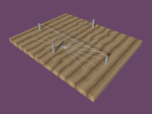
This was the dial that Hugo Michnik invented and studied. By simplifying the general example so:

  • the wires cross orthogonally- one running north-south and the other east-west
  • The east west wire passes under the north south dial, so the (latitude)

the shadow is thrown on a dial-plate marked out like a simple equatorial sundial.

The proof

The first wire is orientated north-south at a constant distance from the dial plate
The second wire is orientated east-west at a constant distance from the dial plate (thus is orthogonal to which lies on the plane of the meridian ).

In this proof (pronounced phi) is the latitude of the dial plate.

Respectively, and are the vertical projections of wires and on the dial plate .

Point is the point on the dial plate directly under the two wires' intersection.
That point is the origin of the X,Y co-ordinate system referred to below.

The X-axis is the east–west line passing through the origin. The Y-axis is the north–south line passing through the origin. The positive Y direction is northward.

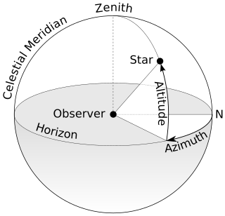
One can show that if the position of the sun is known and determined by the spherical coordinates et (pronounced t-dot and delta, respectively the known as the hour angle et declination), the co-ordinates and of point , the intersection on the two shadows on the dial-plate have values of :

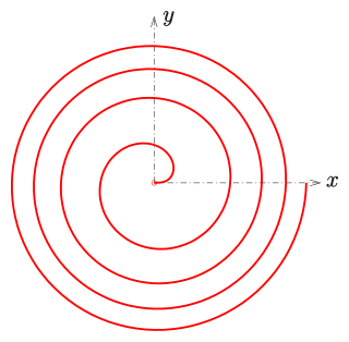
Eliminating the variable in the two preceding equations, one obtains a new equation defined for and which gives, as a function of the latitude and the solar hour angle solaire , the equation of the trace of the sun associated with the local apparent time. In its simplest form this equation is written:

This relation shows that the hour traces are indeed line segments and the meeting-point of these line segments is the point :

In other words, point C is south of point O (where the wires intersect), by a distance of , where is the latitude. [1]

Special case

If one arranges the two wire heights and such :

then the equation for the hour lines can be simply written as:

at all times, the intersection of the shadows on the dial plate is such that the angle is equal to the hour angle of the sun so thus represents solar time.

So provided the sundial respects the la condition the trace of the sun corresponds to the hour-angle shown by lines (rays) centred on the point and the 13 rays that correspond to the hours 6:00, 7:00, 8:00, 9:00... 15:00, 16:00, 17:00, 18:00 are regularly spaced at a constant angle of 15°, about point C. [lower-alpha 1] [1]

A practical example

A London dial is the name given to dials set for 51° 30' N. A simple London bifilar dial has a dial plate with 13 line segments drawn outward from a centre-point C, with each hour's line drawn 15° clockwise from the previous hour's line. The midday line is aligned towards the north.

The north–south wire is 10 cm () above the midday line. That east-west wire is placed at a height of 7.826 () centimeters- equivalent to 10 cm x sin(51° 30'). This passes through C. The east–west wire crosses the north–south wire 6.275 cm north of the centre-point C- that being the equivalent of - 7.826 () divided by tan (51° 30').

Reclining-declining bifilar sundials

Whether a sundial is a bifilar, or whether it's the familiar flat-dial with a straight style (like the usual horizontal and vertical-declining sundials), making it reclining, vertical-declining, or reclining-declining is exactly the same. The declining or reclining-declining mounting is achieved in exactly the same manner, whether the dial is bifilar, or the usual straight-style flat dial.

For any flat-dial, whether bifilar, or ordinary straight-style, the north celestial pole has a certain altitude, measured from the plane of the dial.

  1. Effective latitude:If that dial-plane is horizontal, then it's a horizontal dial (bifilar, or straight-style). Then, of course the north celestial pole's altitude, measured from the dial-plane, is the latitude of the location. Well then, if the flat-dial is reclined, declined, or reclined-&-declined, everything is the same as if it the dial were horizontal, with the celestial pole's altitude, measured with respect to the dial-plane, treated as the latitude.
  2. Dial-North:Likewise, the north celestial pole's longitude, measured with respect to the plane of the dial, with respect to the downward direction (or the direction that a marble would roll, if the dial is reclining) on the dial-face, is the direction that is treated as north, when drawing the hour-lines. I'll call that direction "dial-north".
  3. Equatorial Longitude (hour-angle) of dial-north:It's necessary to find the equatorial longitude of the dial-north direction (drawn on the dial). In the case of the horizontal dial, of course that's an hour-angle of zero, the south meridian. That determines what time ("dial-north time") is represented by the dial-north line. Other times, before and after that, can then have their lines drawn according to their differences from dial-north time—in the same way as they' be drawn on a horizontal dial-face according to their differences from 12 noon (true solar time).


Related Research Articles

Catenary Plane curve formed by a hanging cable

In physics and geometry, a catenary is the curve that an idealized hanging chain or cable assumes under its own weight when supported only at its ends.

Eulers formula Expression of the complex exponential in terms of sine and cosine

Euler's formula, named after Leonhard Euler, is a mathematical formula in complex analysis that establishes the fundamental relationship between the trigonometric functions and the complex exponential function. Euler's formula states that for any real number x:

Mercator projection Map projection for navigational use that distorts areas far from the equator

The Mercator projection is a cylindrical map projection presented by Flemish geographer and cartographer Gerardus Mercator in 1569. It became the standard map projection for navigation because it is unique in representing north as up and south as down everywhere while preserving local directions and shapes. The map is thereby conformal. As a side effect, the Mercator projection inflates the size of objects away from the equator. This inflation is very small near the equator but accelerates with increasing latitude to become infinite at the poles. So, for example, landmasses such as Greenland and Antarctica appear far larger than they actually are relative to landmasses near the equator, such as Central Africa.

Polar coordinate system Two-dimensional coordinate system where each point is determined by a distance from reference point and an angle from a reference direction

In mathematics, the polar coordinate system is a two-dimensional coordinate system in which each point on a plane is determined by a distance from a reference point and an angle from a reference direction. The reference point is called the pole, and the ray from the pole in the reference direction is the polar axis. The distance from the pole is called the radial coordinate, radial distance or simply radius, and the angle is called the angular coordinate, polar angle, or azimuth. The radial coordinate is often denoted by r or ρ, and the angular coordinate by φ, θ, or t. Angles in polar notation are generally expressed in either degrees or radians.

Spherical coordinate system 3-dimensional coordinate system

In mathematics, a spherical coordinate system is a coordinate system for three-dimensional space where the position of a point is specified by three numbers: the radial distance of that point from a fixed origin, its polar angle measured from a fixed zenith direction, and the azimuthal angle of its orthogonal projection on a reference plane that passes through the origin and is orthogonal to the zenith, measured from a fixed reference direction on that plane. It can be seen as the three-dimensional version of the polar coordinate system.

Azimuth The angle between a reference plane and a point

An azimuth is an angular measurement in a spherical coordinate system. The vector from an observer (origin) to a point of interest is projected perpendicularly onto a reference plane; the angle between the projected vector and a reference vector on the reference plane is called the azimuth.

Sundial Device that tells the time of day by the apparent position of the Sun in the sky

A sundial is a device that tells the time of day when there is sunlight by the apparent position of the Sun in the sky. In the narrowest sense of the word, it consists of a flat plate and a gnomon, which casts a shadow onto the dial. As the Sun appears to move across the sky, the shadow aligns with different hour-lines, which are marked on the dial to indicate the time of day. The style is the time-telling edge of the gnomon, though a single point or nodus may be used. The gnomon casts a broad shadow; the shadow of the style shows the time. The gnomon may be a rod, wire, or elaborately decorated metal casting. The style must be parallel to the axis of the Earth's rotation for the sundial to be accurate throughout the year. The style's angle from horizontal is equal to the sundial's geographical latitude.

In linear algebra, a complex square matrix U is unitary if its conjugate transpose U* is also its inverse, that is, if

Rhumb line Arc crossing all meridians of longitude at the same angle

In navigation, a rhumb line, rhumb, or loxodrome is an arc crossing all meridians of longitude at the same angle, that is, a path with constant bearing as measured relative to true or magnetic north.

Tangent half-angle formula Relates the tangent of half of an angle to trigonometric functions of the entire angle

In trigonometry, tangent half-angle formulas relate the tangent of half of an angle to trigonometric functions of the entire angle. Among these are the following

Gnomonics is the study of the design, construction and use of sundials.

Space-oblique Mercator projection

Space-oblique Mercator projection is a map projection devised in the 1970s for preparing maps from Earth-survey satellite data. It is a generalization of the oblique Mercator projection that incorporates the time evolution of a given satellite ground track to optimize its representation on the map. The oblique Mercator projection, on the other hand, optimizes for a given geodesic.

The main trigonometric identities between trigonometric functions are proved, using mainly the geometry of the right triangle. For greater and negative angles, see Trigonometric functions.

Cassini projection

The Cassini projection is a map projection described by César-François Cassini de Thury in 1745. It is the transverse aspect of the equirectangular projection, in that the globe is first rotated so the central meridian becomes the "equator", and then the normal equirectangular projection is applied. Considering the earth as a sphere, the projection is composed of the operations:

Analemmatic sundial

Analemmatic sundials are a type of horizontal sundial that has a vertical gnomon and hour markers positioned in an elliptical pattern. The gnomon is not fixed and must change position daily to accurately indicate time of day. Hence there are no hour lines on the dial and the time of day is read only on the ellipse. As with most sundials, analemmatic sundials mark solar time rather than clock time. An analemmatic sundial is completely defined by

  1. The size of its ellipse.
  2. The latitude of its location.
  3. The declination of the sun.

In spherical astronomy, the parallactic angle is the angle between the great circle through a celestial object and the zenith, and the hour circle of the object. It is usually denoted q. In the triangle zenith—object—celestial pole, the parallactic angle will be the position angle of the zenith at the celestial object. Despite its name, this angle is unrelated with parallax. The parallactic angle is zero or 180° when the object crosses the meridian.

Dialing scales are used to lay out the face of a sundial geometrically. They were proposed by Samuel Foster in 1638, and produced by George Serle and Anthony Thompson in 1658 on a ruler. There are two scales: the latitude scale and the hour scale. They can be used to draw all gnomonic dials – and reverse engineer existing dials to discover their original intended location.

A schema for horizontal dials is a set of instructions used to construct horizontal sundials using compass and straightedge construction techniques, which were widely used in Europe from the late fifteenth century to the late nineteenth century. The common horizontal sundial is a geometric projection of an equatorial sundial onto a horizontal plane.

Schema for vertical declining dials

Vertical declining dials are sundials that indicate local apparent time. Vertical south dials are a special case: as are vertical north, vertical east and vertical west dials. The word declining means that the wall is offset from one of these 4 cardinal points. There are dials that are not vertical, and these are called reclining dials.

References

Footnotes
  1. This property was named the homogeneity of hour lines ' French: homogénéité des lignes horaires by the French mathematician Dominique Collin.
Notes
  1. 1 2 3 4 Michnik 1922.
  2. Beiträge zur Theorie der Sonnenuhren, Leipzig, 1914
  3. Collin 2000.
Bibliography