
In aviation, the instrument landing system (ILS) is a precision radio navigation system that provides short-range guidance to aircraft to allow them to approach a runway at night or in bad weather. In its original form, it allows an aircraft to approach until it is 200 feet (61 m) over the ground, within a 1⁄2 mile (800 m) of the runway. At that point the runway should be visible to the pilot; if it is not, they perform a missed approach. Bringing the aircraft this close to the runway dramatically increases the range of weather conditions in which a safe landing can be made. Other versions of the system, or "categories", have further reduced the minimum altitudes, runway visual ranges (RVRs), and transmitter and monitoring configurations designed depending on the normal expected weather patterns and airport safety requirements.

A non-directional beacon (NDB) or non-directional radio beacon is a radio beacon which does not include inherent directional information. Radio beacons are radio transmitters at a known location, used as an aviation or marine navigational aid. NDB are in contrast to directional radio beacons and other navigational aids, such as low-frequency radio range, VHF omnidirectional range (VOR) and tactical air navigation system (TACAN).

In aviation, distance measuring equipment (DME) is a radio navigation technology that measures the slant range (distance) between an aircraft and a ground station by timing the propagation delay of radio signals in the frequency band between 960 and 1215 megahertz (MHz). Line-of-visibility between the aircraft and ground station is required. An interrogator (airborne) initiates an exchange by transmitting a pulse pair, on an assigned 'channel', to the transponder ground station. The channel assignment specifies the carrier frequency and the spacing between the pulses. After a known delay, the transponder replies by transmitting a pulse pair on a frequency that is offset from the interrogation frequency by 63 MHz and having specified separation.

An instrument landing system localizer, or simply localizer, is a system of horizontal guidance in the instrument landing system, which is used to guide aircraft along the axis of the runway.
A tactical air navigation system, commonly referred to by the acronym TACAN, is a navigation system used by military aircraft. It provides the user with bearing and distance to a ground or ship-borne station. It is from an end-user perspective a more accurate version of the VOR/DME system that provides bearing and range information for civil aviation. The DME portion of the TACAN system is available for civil use; at VORTAC facilities where a VOR is combined with a TACAN, civil aircraft can receive VOR/DME readings. Aircraft equipped with TACAN avionics can use this system for enroute navigation as well as non-precision approaches to landing fields.
Airband or aircraft band is the name for a group of frequencies in the VHF radio spectrum allocated to radio communication in civil aviation, sometimes also referred to as VHF, or phonetically as "Victor". Different sections of the band are used for radionavigational aids and air traffic control.

In aviation, an instrument approach or instrument approach procedure (IAP) is a series of predetermined maneuvers for the orderly transfer of an aircraft operating under instrument flight rules from the beginning of the initial approach to a landing, or to a point from which a landing may be made visually. These approaches are approved in the European Union by EASA and the respective country authorities and in the United States by the FAA or the United States Department of Defense for the military. The ICAO defines an instrument approach as "a series of predetermined maneuvers by reference to flight instruments with specific protection from obstacles from the initial approach fix, or where applicable, from the beginning of a defined arrival route to a point from which a landing can be completed and thereafter, if landing is not completed, to a position at which holding or en route obstacle clearance criteria apply."
The microwave landing system (MLS) is an all-weather, precision radio guidance system intended to be installed at large airports to assist aircraft in landing, including 'blind landings'. MLS enables an approaching aircraft to determine when it is aligned with the destination runway and on the correct glidepath for a safe landing. MLS was intended to replace or supplement the instrument landing systems (ILS). MLS has a number of operational advantages over ILS, including a wider selection of channels to avoid interference with nearby installations, excellent performance in all weather, a small "footprint" at the airports, and wide vertical and horizontal "capture" angles that allowed approaches from wider areas around the airport.

Precision approach radar orPAR is a type of radar guidance system designed to provide lateral and vertical guidance to an aircraft pilot for landing, until the landing threshold is reached. Controllers monitoring the PAR displays observe each aircraft's position and issue instructions to the pilot that keep the aircraft on course and glidepath during final approach. After the aircraft reaches the decision height (DH) or decision altitude (DA), further guidance is advisory only. The overall concept is known as ground-controlled approach (GCA), and this name was also used to refer to the radar systems in the early days of its development.
The air traffic control radar beacon system (ATCRBS) is a system used in air traffic control (ATC) to enhance surveillance radar monitoring and separation of air traffic. It consists of a rotating ground antenna and transponders in aircraft. The ground antenna sweeps a narrow vertical beam of microwaves around the airspace. When the beam strikes an aircraft, the transponder transmits a return signal back giving information such as altitude and the Squawk Code, a four digit code assigned to each aircraft that enters a region. Information about this aircraft is then entered into the system and subsequently added to the controller's screen to display this information when queried. This information can include flight number designation and altitude of the aircraft. ATCRBS assists air traffic control (ATC) surveillance radars by acquiring information about the aircraft being monitored, and providing this information to the radar controllers. The controllers can use the information to identify radar returns from aircraft and to distinguish those returns from ground clutter.

A marker beacon is a particular type of VHF radio beacon used in aviation, usually in conjunction with an instrument landing system (ILS), to give pilots a means to determine position along an established route to a destination such as a runway.

A transponder landing system (TLS) is an all-weather, precision landing system that uses existing airborne transponder and instrument landing system (ILS) equipment to create a precision approach at a location where an ILS would normally not be available.

The Rebecca/Eureka transponding radar was a short-range radio navigation system used for the dropping of airborne forces and their supplies. It consisted of two parts, the Rebecca airborne transceiver and antenna system, and the Eureka ground-based transponder. Rebecca calculated the range to the Eureka based on the timing of the return signals, and its relative position using a highly directional antenna. The 'Rebecca' name comes from the phrase "Recognition of beacons". The 'Eureka' name comes from the Greek word meaning "I have found it!".
The Lorenz beam was a blind-landing radio navigation system developed by C. Lorenz AG in Berlin. The first system had been installed in 1932 at Berlin-Tempelhof Central Airport, followed by Dübendorf in Switzerland (1934) and others all over the world. The Lorenz company referred to it simply as the Ultrakurzwellen-Landefunkfeuer, German for "ultra-short-wave landing radio beacon", or LFF. In the UK it was known as Standard Beam Approach (SBA).

In navigation, a radio beacon or radiobeacon is a kind of beacon, a device that marks a fixed location and allows direction-finding equipment to find relative bearing. But instead of employing visible light, radio beacons transmit electromagnetic radiation in the radio wave band. They are used for direction-finding systems on ships, aircraft and vehicles.
During World War II, the German Luftwaffe relied on an increasingly diverse array of electronic communications, IFF and RDF equipment as avionics in its aircraft and also on the ground. Most of this equipment received the generic prefix FuG for Funkgerät, meaning "radio equipment". Most of the aircraft-mounted Radar equipment also used the FuG prefix. This article is a list and a description of the radio, IFF and RDF equipment.
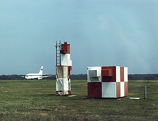
The AN/MRN-1 was an instrument approach localizer used by the Army Air Force during and after World War II. It was standardized on 3 July 1942. It replaced the SCR-241, and was a component of SCS-51.
The AN/MRN-3 was a marker beacon set used by the Army Air Force during and after World War II, it was standardized 23 October 1943, and replaced SCR-241.
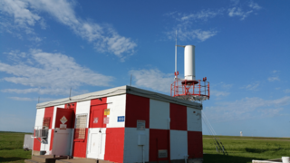
In aviation, instrument landing system glide path, commonly referred to as a glide path (G/P) or glide slope (G/S), is "a system of vertical guidance embodied in the instrument landing system which indicates the vertical deviation of the aircraft from its optimum path of descent".