A two-strokeengine is a type of internal combustion engine that completes a power cycle with two strokes of the piston during one power cycle, this power cycle being completed in one revolution of the crankshaft. A four-stroke engine requires four strokes of the piston to complete a power cycle during two crankshaft revolutions. In a two-stroke engine, the end of the combustion stroke and the beginning of the compression stroke happen simultaneously, with the intake and exhaust functions occurring at the same time.
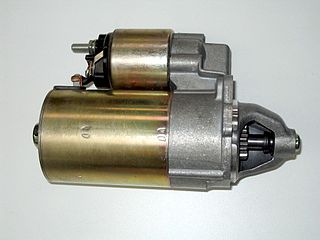
A starter is a device used to rotate (crank) an internal-combustion engine so as to initiate the engine's operation under its own power. Starters can be electric, pneumatic, or hydraulic. The starter can also be another internal-combustion engine in the case, for instance, of very large engines, or diesel engines in agricultural or excavation applications.

A camshaft is a shaft that contains a row of pointed cams in order to convert rotational motion to reciprocating motion. Camshafts are used in piston engines, mechanically controlled ignition systems and early electric motor speed controllers.

A four-strokeengine is an internal combustion (IC) engine in which the piston completes four separate strokes while turning the crankshaft. A stroke refers to the full travel of the piston along the cylinder, in either direction. The four separate strokes are termed:
- Intake: Also known as induction or suction. This stroke of the piston begins at top dead center (T.D.C.) and ends at bottom dead center (B.D.C.). In this stroke the intake valve must be in the open position while the piston pulls an air-fuel mixture into the cylinder by producing a partial vacuum in the cylinder through its downward motion.
- Compression: This stroke begins at B.D.C, or just at the end of the suction stroke, and ends at T.D.C. In this stroke the piston compresses the air-fuel mixture in preparation for ignition during the power stroke (below). Both the intake and exhaust valves are closed during this stage.
- Combustion: Also known as power or ignition. This is the start of the second revolution of the four stroke cycle. At this point the crankshaft has completed a full 360 degree revolution. While the piston is at T.D.C. the compressed air-fuel mixture is ignited by a spark plug or by heat generated by high compression, forcefully returning the piston to B.D.C. This stroke produces mechanical work from the engine to turn the crankshaft.
- Exhaust: Also known as outlet. During the exhaust stroke, the piston, once again, returns from B.D.C. to T.D.C. while the exhaust valve is open. This action expels the spent air-fuel mixture through the exhaust port.
Engine tuning is the adjustment or modification of the internal combustion engine or Engine Control Unit (ECU) to yield optimal performance and increase the engine's power output, economy, or durability. These goals may be mutually exclusive; an engine may be de-tuned with respect to output power in exchange for better economy or longer engine life due to lessened stress on engine components.

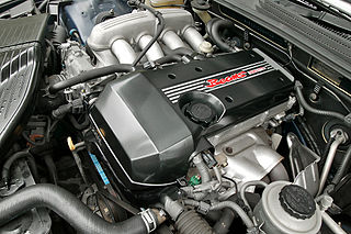
VTEC is a system developed by Honda to improve the volumetric efficiency of a four-stroke internal combustion engine, resulting in higher performance at high RPM, and lower fuel consumption at low RPM. The VTEC system uses two camshaft profiles and hydraulically selects between profiles. It was invented by Honda engineer Ikuo Kajitani. It is distinctly different from standard VVT systems which change only the valve timings and do not change the camshaft profile or valve lift in any way.

Variable valve timing (VVT) is the process of altering the timing of a valve lift event in an internal combustion engine, and is often used to improve performance, fuel economy or emissions. It is increasingly being used in combination with variable valve lift systems. There are many ways in which this can be achieved, ranging from mechanical devices to electro-hydraulic and camless systems. Increasingly strict emissions regulations are causing many automotive manufacturers to use VVT systems.
The GM Ecotec engine, also known by its codename L850, is a family of all-aluminium inline-four engines, displacing between 1.4 and 2.5 litres. Confusingly, the Ecotec name was also applied to both the Buick V6 Engine when used in Holden Vehicles, as well as the final DOHC derivatives of the previous GM Family II engine; the architecture was substantially re-engineered for this new Ecotec application produced since 2000. This engine family replaced the GM Family II engine, the GM 122 engine, the Saab H engine, and the Quad 4 engine. It is manufactured in multiple locations, to include Spring Hill Manufacturing, in Spring Hill, Tennessee, with engine blocks and cylinder heads cast at Saginaw Metal Casting Operations in Saginaw, Michigan.

The powerplant used in Saturn S-Series automobiles was a straight-4 aluminum piston engine produced by Saturn, a subsidiary of General Motors. The engine was only used in the Saturn S-series line of vehicles from 1991 through 2002. It was available in chain-driven SOHC or DOHC variants.

A tappet is a valve train component which converts rotating motion into linear motion in activating a valve. It is most commonly found in internal combustion engines, which converts the rotating motion of the camshaft into linear motion of intake and exhaust valves, either directly or indirectly.
The Toyota S Series engines are a family of straight-four petrol engines with displacements between 1.8 and 2.2 litres, produced by Toyota Motor Corporation from January 1980 to August 2007. The S series has cast iron engine blocks and aluminium cylinder heads.
A camless or free-valve piston engine is an engine that has poppet valves operated by means of electromagnetic, hydraulic, or pneumatic actuators instead of conventional cams. Actuators can be used to both open and close valves, or to open valves closed by springs or other means.
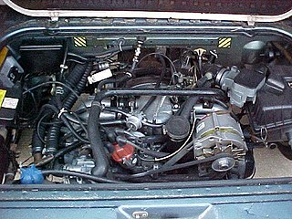
The Volkswagen wasserboxer is a four cylinder horizontally opposed pushrod overhead-valve (OHV) petrol engine developed by Volkswagen. The engine is water-cooled, and takes its name from the German: "wasserboxer" ("Water-boxer"); with "boxer" being another term for horizontally opposed engines. It was available in two displacements – either a 1.9-litre or a 2.1-litre; the 2.1-litre being a longer stroke version of the 1.9-litre, both variants sharing the same cylinder bore. This engine was unique to the Volkswagen Type 2 (T3), having never been used in any other vehicle. Volkswagen contracted Oettinger to develop a six-cylinder version of this engine. Volkswagen decided not to use it, but Oettinger sold a Volkswagen Type 2 (T3) equipped with this engine.
A hydraulic tappet, also known as a hydraulic valve lifter or hydraulic lash adjuster, is a device for maintaining zero valve clearance in an internal combustion engine. Conventional solid valve lifters require regular adjusting to maintain a small clearance between the valve and its rocker or cam follower. This space prevents the parts from binding as they expand with the engine's heat, but can also lead to noisy operation and increased wear as the parts rattle against one another until they reach operating temperature. The hydraulic lifter was designed to compensate for this small tolerance, allowing the valve train to operate with zero clearance—leading to quieter operation, longer engine life, and eliminating the need for periodic adjustment of valve clearance.

A hydraulic motor is a mechanical actuator that converts hydraulic pressure and flow into torque and angular displacement (rotation). The hydraulic motor is the rotary counterpart of the hydraulic cylinder as a linear actuator. Most broadly, the category of devices called hydraulic motors has sometimes included those that run on hydropower but in today's terminology the name usually refers more specifically to motors that use hydraulic fluid as part of closed hydraulic circuits in modern hydraulic machinery.

In a spark ignition internal combustion engine, ignition timing is the timing, relative to the current piston position and crankshaft angle, of the release of a spark in the combustion chamber near the end of the compression stroke.
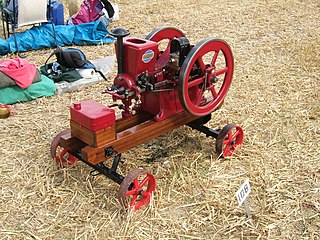
A hit-and-miss engine or Hit 'N' Miss is a type of stationary internal combustion engine that is controlled by a governor to only fire at a set speed. They are usually 4-stroke but 2-stroke versions were made. It was conceived in the late 19th century and produced by various companies from the 1890s through approximately the 1940s. The name comes from the speed control on these engines: they fire ("hit") only when operating at or below a set speed, and cycle without firing ("miss") when they exceed their set speed. This is as compared to the "throttle governed" method of speed control. The sound made when the engine is running without a load is a distinctive "Snort POP whoosh whoosh whoosh whoosh snort POP" as the engine fires and then coasts until the speed decreases and it fires again to maintain its average speed. The snorting is caused by the atmospheric intake valve used on many of these engines.

The oil pump is an internal combustion engine part that circulates engine oil under pressure to the rotating bearings, the sliding pistons and the camshaft of the engine. This lubricates the bearings, allows the use of higher-capacity fluid bearings and also assists in cooling the engine.
The term power assembly refers to an Electro-Motive Diesel (EMD) engine sub-assembly designed to be "easily" removed and replaced in order to restore engine performance lost to wear or engine failure. Typical of heavy-duty internal combustion engines used in industrial applications, EMD engines are designed to allow the cylinder liners, pistons, piston rings and connecting rods to be replaced at overhaul without removing the entire engine assembly from its application location. This increases engine value, reduces downtime and allows the engine to be returned to true new engine performance. Other terms such as cylinder pack, liner pack, cylinder assembly and cylinder kit are used in the engine industry to describe similar assemblies. In the large-engine industry, the term "power assembly" has also become generic and is often used to refer to the assemblies used in non-EMD engines where "power pack" may be the preferred term, although both terms are functionally the same.

The Leyland L60 was a British 19-litre (1,200 cu in) vertical six-cylinder opposed-piston two-stroke multi-fuel diesel engine designed by Leyland Motors in the late 1950s/early 1960s for the Chieftain main battle tank (MBT). The engine was also used in the Vickers MBT and its Indian-built derivative, the Vijayanta.