Carbon nanotube nanomotor

Last updated

A device generating linear or rotational motion using carbon nanotube(s) as the primary component, is termed a nanotube nanomotor. Nature already has some of the most efficient and powerful kinds of nanomotors. Some of these natural biological nanomotors have been re-engineered to serve desired purposes. However, such biological nanomotors are designed to work in specific environmental conditions (pH, liquid medium, sources of energy, etc.). Laboratory-made nanotube nanomotors on the other hand are significantly more robust and can operate in diverse environments including varied frequency, temperature, mediums and chemical environments. The vast differences in the dominant forces and criteria between macroscale and micro/nanoscale offer new avenues to construct tailor-made nanomotors. The various beneficial properties of carbon nanotubes makes them the most attractive material to base such nanomotors on.

Contents

History

Just fifteen years after making the world's first micrometer-sized motor, Alex Zettl led his group at University of California at Berkeley to construct the first nanotube nanomotor in 2003. A few concepts and models have been spun off ever since including the nanoactuator driven by a thermal gradient as well as the conceptual electron windmill, both of which were revealed in 2008.

Size effects

Electrostatic forces

Coulomb's law states that the electrostatic force between two objects is inversely proportional to the square of their distance. Hence, as the distance is reduced to less than a few micrometers, a large force can be generated from seemingly small charges on two bodies. However, electrostatic charge scales quadratically, thereby the electrostatic force also scales quadratically, as the following equations show:

Alternatively

[1]

Here A is area, C is capacitance, F is electrostatic force, E is electrostatic field, L is length, V is voltage and Q is charge. Despite the scaling nature of the electrostatic force it is one of the major mechanisms of sensing and actuation in the field of microelectromechanical systems (MEMS) and is the backbone for the working mechanism of the first NEMS nanomotor. The quadratic scaling is alleviated by increasing the number of units generating the electrostatic force as seen in comb drives in many MEMS devices.

Friction

Just as the electrostatic force, the frictional force scales quadratically with size F ~ L2. [2]

Friction is an ever plaguing problem regardless of the scale of a device. It becomes all the more prominent when a device is scaled down. In the nano scale it can wreak havoc if not accounted for because the parts of a Nano-Electro-Mechanical-Systems (NEMS) device are sometimes only a few atoms thick. Furthermore, such NEMS devices typically have a very large surface area-to-volume ratio. Surfaces in the nanoscale resemble a mountain range, where each peak corresponds to an atom or a molecule. Friction at the nanoscale is proportional to the number of atoms that interact between two surfaces. Hence, friction between perfectly smooth surfaces in the macroscale is actually similar to large rough objects rubbing against each other. [3]

In the case of nanotube nanomotors however, the intershell friction in the multi-walled nanotubes (MWNT) is remarkably small. Molecular dynamics studies show that, with the exception of small peaks, the frictional force remains almost negligible for all sliding velocities until a special sliding velocity is reached. Simulations relating the sliding velocity, induced rotation, inter-shell frictional force to the applied force provide explanations for the low inter-wall friction. Contrary to macroscale expectations the speed at which an inner tube travels within an outer tube does not follow a linear relationship with the applied force. Instead, the speed remains constant (as in a plateau) despite increasing applied force occasionally jumping in value to the next plateau. No real rotation is noticed in nonchiral inner tubes. In the case of chiral tubes a true rotation is noticed and the angular velocity also jumps to plateaus along with the jumps in the linear velocity. These plateaus and jumps can be explained as a natural outcome of frictional peaks for growing velocity, the stable (rising) side of the peak leading to a plateau, the dropping (unstable) side leading to a jump. These peaks occur due to parametric excitation of vibrational modes in the walls of the tubes due to the sliding of the inner tube. With the exception of small peaks, that correspond to the speed plateaus, the frictional force remains almost negligible for all sliding velocities until a special sliding velocity. These velocity plateaus correspond to the peaks in the frictional force. The sudden rise in sliding velocity is due to a resonance condition between a frequency that is dependent on the inter-tube corrugation period and particular phonon frequencies of the outer tube which happen to possess a group velocity approximately equal to the sliding velocity. [4]

First NEMS nanomotor

The first nanomotor can be thought of as a scaled down version of a comparable microelectromechanical systems (MEMS) motor. The nanoactuator consists of a gold plate rotor, rotating about the axis of a multi-walled nanotube (MWNT). The ends of the MWNT rest on a SiO2 layer which form the two electrodes at the contact points. Three fixed stator electrodes (two visible 'in-plane' stators and one 'gate' stator buried beneath the surface) surround the rotor assembly. Four independent voltage signals (one to the rotor and one to each stators) are applied to control the position, velocity and direction of rotation. Empirical angular velocities recorded provide a lower bound of 17 Hz (although capable of operating at much higher frequencies) during complete rotations. [5]

Fabrication

The MWNTs are synthesized by the arc-discharge technique, suspended in 1,2-dichlorobenzene and deposited on degenerately doped silicon substrates with a 1 μm of SiO2. The MWNT can be aligned according to pre-made markings on the substrate by using an atomic force microscope (AFM) or a scanning electron microscope (SEM). The rotor, electrodes and the 'in-plane' stators are patterned using electron beam lithography using an appropriately masked photo-resist. Gold with a chromium adhesion layer is thermally evaporated, lifted off in acetone and then annealed at 400 °C to ensure better electrical and mechanical contact with the MWNT. The rotor measures 250–500 nm on a side. An HF etch is then used to remove sufficient thickness (500 nm of SiO2) of the substrate to make room for the rotor when it rotates. The Si substrate serves as the gate stator. The MWNT at this point displays a very high torsional spring constant (10−15 to 10−13 N m with resonant frequencies in the tens of megahertz), hence, preventing large angular displacements. To overcome this, one or more outer MWNT shells are compromised or removed in the region between the anchors and the rotor plate. One simple way to accomplish this is by successively applying very large stator voltages (around 80 V DC) that cause mechanical fatigue and eventually shear the outer shells of the MWNT. An alternative method involves the reduction of the outermost MWNT tubes to smaller, wider concentric nanotubes beneath the rotor plate. [5]

The smaller nanotube(s) are fabricated using the Electrical driven vaporization (EDV) which is a variant of the electrical-breakdown technique. Passing current between the two electrodes typically results in failure of the outermost shell only on one side of the nanotube. Current is therefore passed between one electrode and the center of the MWNT which results in the failure of the outermost shell between this electrode and the center. The process is repeated on the opposite side to result in the formation of the short concentric nanotube that behaves like a low friction bearing along the longer tube. [6]

Arrays of nanoactuators

Due to the minuscule magnitude of output generated by a single nanoactuator the necessity to use arrays of such actuators to accomplish a higher task comes into picture. Conventional methods like chemical vapor deposition (CVD) allow the exact placement of nanotubes by growing them directly on the substrate. However, such methods are unable to produce very high qualities of MWNT. Moreover, CVD is a high temperature process that would severely limit the compatibility with other materials in the system. A Si substrate is coated with electron beam resist and soaked in acetone to leave only a thin polymer layer. The substrate is selectively exposed to a low energy electron beam of an SEM that activates the adhesive properties of the polymer later. This forms the basis for the targeting method. The alignment method exploits the surface velocity obtained by a fluid as it flows off a spinning substrate. MWNTs are suspended in orthodicholrobenzene (ODCB) by ultrasonication in an Aquasonic bath that separates most MWNT bundles into individual MWNTs. Drops of this suspension are then pipetted one by one onto the center of a silicon substrate mounted on a spin coater rotating at 3000 rpm. Each subsequent drop of the suspension is pipetted only after the previous drop has completely dried to ensure larger density and better alignment of the MWNTs (90% of the MWNTs over 1 μm long lie within 1°). Standard electron beam lithography is used to pattern the remaining components of the nanoactuators. [7]

Arc-discharge evaporation technique

Figure 1.3: Cartoon showing the basic experimental setup for the arc-discharge technique of large scale carbon nanotube synthesis Arc discharge nanotube.png
Figure 1.3: Cartoon showing the basic experimental setup for the arc-discharge technique of large scale carbon nanotube synthesis

This technique is a variant of the standard arc-discharge technique used for the synthesis of fullerenes in an inert gas atmosphere. As Figure 1.3 shows, the experiment is carried out in a reaction vessel containing an inert gas such as helium, argon, etc. flowing at a constant pressure. A potential of around 18 V is applied across two graphite electrodes (diameters of the anode and cathode are 6 mm and 9 mm) separated by a short distance of usually 1–4 mm within this chamber. The amount of current (usually 50–100 A) passed through the electrodes to ensure nanotube formation depends on the dimensions of the electrodes, separation distance and the inert gas used. As a result, carbon atoms are ejected from the anode and are deposited onto the cathode hence shrinking the mass of the anode and increasing the mass of the cathode. The black carbonaceous deposit (a mixture of nanoparticles and nanotubes in a ratio of 1:2) is seen growing on the inside of the cathode while a hard grey metallic shell forms on the outside. The total yield of nanotubes as a proportion of starting graphitic material peaks at a pressure of 500 torr at which point 75% of graphite rod consumed is converted to nanotubes. The nanotubes formed range from 2 to 20 nm in diameter and few to several micrometers in length. [8] There are several advantages of choosing this method over the other techniques such as laser ablation and chemical vapor deposition such as fewer structural defects (due to high growth temperature), better electrical, mechanical and thermal properties, high production rates (several hundred mg in ten minutes), etc. [9]

Electrical-breakdown technique

Figure 1.4: (A) Graph showing remarkably discrete, constant drops in conductance for the removal of each subsequent carbon shell under constant voltage (B) Images of partially broken MWNTs show clear thinning, with a decrease in radius equal to the intershell spacing (0.34 nm) times the number of completed breakdown steps. The two segments of this sample were independently thinned by 3 and 10 shells, as depicted by the color overlays Electrical breakdown tubes.png
Figure 1.4: (A) Graph showing remarkably discrete, constant drops in conductance for the removal of each subsequent carbon shell under constant voltage (B) Images of partially broken MWNTs show clear thinning, with a decrease in radius equal to the intershell spacing (0.34 nm) times the number of completed breakdown steps. The two segments of this sample were independently thinned by 3 and 10 shells, as depicted by the color overlays

Large-scale synthesis of carbon nanotubes typically results in a randomly varied proportion of different types of carbon nanotubes. Some may be semiconducting while others may be metallic in their electrical properties. Most applications require the use of such specific types of nanotubes. Electrical-breakdown technique provides a means for separating and selecting desired type of nanotubes. Carbon nanotubes are known to withstand very large current densities up to 109 A/cm2 partly due to the strong sigma bonds between carbon atoms. However, at sufficiently high currents the nanotubes fail primarily due to rapid oxidation of the outermost shell. This results in a partial conductance drop that becomes apparent within a few seconds. Applying an increased bias displays multiple independent and stepwise drops in conductance (figure 1.4) resulting from the sequential failure of carbon shells. Current in a MWNT typically travels in the outermost shell due to the direct contact between this shell and the electrodes. This controlled destruction of shells without affecting disturbing inner layers of MWNTs permits the effective separation of the nanotubes. [10]

Principle

The rotor is made to rotate using electrostatic actuation. An out-of-phase common frequency sinusoidal voltages to two in-plane stators S1, S2, a doubled frequency voltage signal to the gate stator S3 and a DC offset voltage to the rotor plate R are applied as shown below:

By the sequential application of these asymmetrical stator voltages (less than 5 V) the rotor plate can be drawn to successive stators hence making the plate complete rotations. The high proximity between the stators and the rotor plate is one reason why a large force is not required for electrostatic actuation. Reversing the bias causes the rotor to rotate in the opposite direction as expected. [5]

Applications

Thermal gradient driven nanotube actuators

Figure 2.1: Thermal gradient driven nanomotor. (A & B): SEM images of experimental setup. (C) Schematic of the nanomotor also displaying degrees of freedom Thermal nanomotor1.jpg
Figure 2.1: Thermal gradient driven nanomotor. (A & B): SEM images of experimental setup. (C) Schematic of the nanomotor also displaying degrees of freedom

The nanoactuator, as shown in Figure 2.1 comprises two electrodes connected via a long MWNT. A gold plate acts as the cargo and is attached to a shorter and wider concentric nanotube. The cargo moves towards the cooler electrode (Figure 2.2) due to the thermal gradient in the longer nanotube induced by the high current that is passed through it. The maximum velocity was approximated to 1 μm/s which is comparable to the speeds attained by kinesin biomotors. [11]

Fabrication

The MWNT are fabricated using the standard arc-discharge evaporation process and deposited on an oxidized silicon substrate. The gold plate in the center of the MWNT is patterned using electron-beam lithography and Cr/Au evaporation. During the same process, the electrodes are attached to the nanotube. Finally, electrical-breakdown technique is used to selectively remove a few outer walls of the MWNT. Just as the nanoactuator from the Zettl group, this enables low friction rotation and translation of the shorter nanotube along the axis of the longer tube. The application of the electrical-breakdown technique does not result in the removal of the tube(s) below the cargo. This might be because the metal cargo absorbs the heat generated in the portion of the tube in its immediate vicinity hence delaying or possibly even preventing tube oxidation in this part. [11]

Principle

Figure 2.2: Motion of shorter nanotubes (red) along the longer tubes (yellow) from the hotter(top) section of the nanotube to the cooler (bottom) section of the nanotube carrying the metal cargo (gray) Thermal nanomotor6.jpg
Figure 2.2: Motion of shorter nanotubes (red) along the longer tubes (yellow) from the hotter(top) section of the nanotube to the cooler (bottom) section of the nanotube carrying the metal cargo (gray)
Figure 2.3: Degree of translational and rotation are dependent on the chiralities of the two nanotubes Thermal nanometer chirality.png
Figure 2.3: Degree of translational and rotation are dependent on the chiralities of the two nanotubes

The interaction between the longer and shorter tubes generates an energy surface that confines the motion to specific tracks – translation and rotation. The degree of translational and rotational motion of the shorter tube are highly dependent on the chiralities of the two tubes as shown in Figure 2.3. Motion in the nanoactuator displayed a proclivity of the shorter tube to follow a path of minimum energy. This path could either have a roughly constant energy or have a series of barriers. In the former case, friction and vibrational motion of atoms can be neglected whereas a stepwise motion is expected in the latter scenario. [11]

Stepwise motion

The stepwise motion can be explained by the existence of periodic energy barriers for relative motion between the longer and shorter tubes. For a given pair of nanotubes, the ratio of the step in rotation to the step in translation is typically a constant, the value of which depends on the chirality of the nanotubes. The energy of such barriers could be estimated from the temperature in the nanotube, a lower bound for which can be estimated as the melting temperature of gold (1300 K) by noting that the gold plate melts (Figure 2.4) to form a spherical structure as current is passed through the nanomotor. The motion rate γ can be written as a function of the attempt frequency , the Boltzmann constant , and temperature as:

Taking , using the approximation:

where m is the mass of the cargo and represents the contact area, the barrier height is estimated as 17 μeV per atom. [11]

Figure 2.4: SEM images show the transformation of gold plate (left) into a ball (right) due to very high temperatures Thermal nanomotor melting gold.png
Figure 2.4: SEM images show the transformation of gold plate (left) into a ball (right) due to very high temperatures

Mechanism for actuation

Many proposals were made to explain the driving mechanism behind the nanoactuator. The high current (0.1 mA) required to drive the actuator is likely to cause sufficient dissipation to clean the surface of contaminants; hence, ruling out the possibility of contaminants playing a major role. The possibility of electromigration, where the electrons move atomic impurities via momentum transfer due to collisions, was also ruled out because the reversal of the current direction did not affect the direction of displacement. Similarly, rotational motion could not have been caused by an induced magnetic field due to the current passing through the nanotube because the rotation could either be left or right-handed depending on the device. Stray electric field effect could not be the driving factor because the metal plate staid immobile for high resistive devices even under a large applied potential. The thermal gradient in the nanotube provides the best explanation for the driving mechanism. [11]

Thermal gradient induced motion

The induced motion of the shorter nanotube is explained as the reverse of the heat dissipation that occurs in friction wherein the sliding of two objects in contact results in the dissipation of some of the kinetic energy as phononic excitations caused by the interface corrugation. The presence of a thermal gradient in a nanotube causes a net current of phononic excitations traveling from the hotter region to the cooler region. The interaction of these phononic excitations with mobile elements (the carbon atoms in the shorter nanotube) causes the motion of the shorter nanotube. This explains why the shorter nanotube moves towards the cooler electrode. Changing the direction of the current has no effect on the shape of thermal gradient in the longer nanotube. Hence, direction of the movement of the cargo is independent of the direction of the bias applied. The direct dependence of the velocity of the cargo to the temperature of the nanotube is inferred from the fact that the velocity of the cargo decreases exponentially as the distance from the midpoint of the long nanotube increases. [11]

Shortcomings

Figure 2.5: Graph demonstrating the direct relationship between the thermal gradient and the displacement of the shorter tube / cargo Thermal nanomotor thermal gradient.png
Figure 2.5: Graph demonstrating the direct relationship between the thermal gradient and the displacement of the shorter tube / cargo

The temperatures and the thermal gradient that the MWNT are subjected to are very high. On one hand, the high thermal gradient seems to have a highly detrimental effect on the lifetime of such nanoactuators. On the other hand, experiments show that the displacement of the shorter tube is directly proportional to the thermal gradient (see Figure 2.5). Therefore, a compromise needs to be reached to optimize the thermal gradient. The dimensions of movable nanotube is directly related to the energy barrier height. Although the current model excites multiple phonon modes, selective phonon mode excitation would enable lowering the phonon bath temperature. [11]

Applications

Electron windmill

Figure 3.1: MWNT nanomotor (A) and nanodrill (B). CNT windmills.png
Figure 3.1: MWNT nanomotor (A) and nanodrill (B).

Structure

As figure 3.1 shows, the nanomotor consists of a double-walled CNT (DWNT) formed from an achiral (18,0) outer tube clamped to external gold electrodes and a narrower chiral (6,4) inner tube. The central portion of the outer tube is removed using the electrical-breakdown technique to expose the free-to-rotate, inner tube. The nanodrill also comprises an achiral outer nanotube attached to a gold electrode but the inner tube is connected to a mercury bath. [12]

Principle

Conventional nanotube nanomotors make use of static forces that include elastic, electrostatic, friction and van der Waals forces. The electron windmill model makes use of a new "electron-turbine" drive mechanism that obviates that need for metallic plates and gates that the above nanoactuators require. When a DC voltage is applied between the electrodes, a "wind" of electrons is produced from left to right. The incident electron flux in the outer achiral tube initially possesses zero angular momentum, but acquires a finite angular momentum after interacting with the inner chiral tube. By Newton's third law, this flux produces a tangential force (hence a torque) on the inner nanotube causing it to rotate hence giving this model the name – "electron windmill". For moderate voltages, the tangential force produced by the electron wind is much greatly exceed the associated frictional forces. [12]

Applications

Some of the main applications of the electron windmill include:

See also

Related Research Articles

A Langmuir probe is a device used to determine the electron temperature, electron density, and electric potential of a plasma. It works by inserting one or more electrodes into a plasma, with a constant or time-varying electric potential between the various electrodes or between them and the surrounding vessel. The measured currents and potentials in this system allow the determination of the physical properties of the plasma.

<span class="mw-page-title-main">Nanoelectromechanical systems</span> Class of devices for nanoscale functionality

Nanoelectromechanical systems (NEMS) are a class of devices integrating electrical and mechanical functionality on the nanoscale. NEMS form the next logical miniaturization step from so-called microelectromechanical systems, or MEMS devices. NEMS typically integrate transistor-like nanoelectronics with mechanical actuators, pumps, or motors, and may thereby form physical, biological, and chemical sensors. The name derives from typical device dimensions in the nanometer range, leading to low mass, high mechanical resonance frequencies, potentially large quantum mechanical effects such as zero point motion, and a high surface-to-volume ratio useful for surface-based sensing mechanisms. Applications include accelerometers and sensors to detect chemical substances in the air.

<span class="mw-page-title-main">Nanomotor</span> Molecular device capable of converting energy into movement

A nanomotor is a molecular or nanoscale device capable of converting energy into movement. It can typically generate forces on the order of piconewtons.

An electrostatic motor or capacitor motor is a type of electric motor based on the attraction and repulsion of electric charge.

<span class="mw-page-title-main">Comb drive</span>

Comb-drives are microelectromechanical actuators, often used as linear actuators, which utilize electrostatic forces that act between two electrically conductive combs. Comb drive actuators typically operate at the micro- or nanometer scale and are generally manufactured by bulk micromachining or surface micromachining a silicon wafer substrate.

<span class="mw-page-title-main">Potential applications of carbon nanotubes</span>

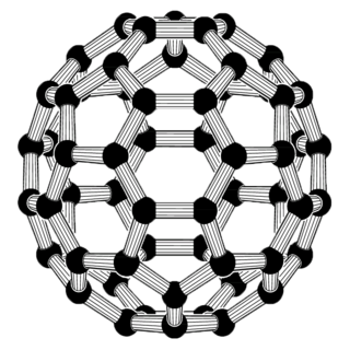
Carbon nanotubes (CNTs) are cylinders of one or more layers of graphene (lattice). Diameters of single-walled carbon nanotubes (SWNTs) and multi-walled carbon nanotubes (MWNTs) are typically 0.8 to 2 nm and 5 to 20 nm, respectively, although MWNT diameters can exceed 100 nm. CNT lengths range from less than 100 nm to 0.5 m.

<span class="mw-page-title-main">Dielectric elastomers</span>

Dielectric elastomers (DEs) are smart material systems that produce large strains and are promising for Soft robotics, Artificial muscle, etc. They belong to the group of electroactive polymers (EAP). DE actuators (DEA) transform electric energy into mechanical work and vice versa. Thus, they can be used as both actuators, sensors, and energy-harvesting devices. They have high elastic energy density and fast response due to being lightweight, highly stretchable, and operating under the electrostatic principle. They have been investigated since the late 1990s. Many prototype applications exist. Every year, conferences are held in the US and Europe.

<span class="mw-page-title-main">Alex Zettl</span> American nano-scale physicist

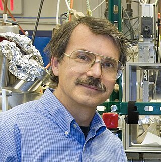
Alex K. Zettl is an American experimental physicist, educator, and inventor.

<span class="mw-page-title-main">Mechanical properties of carbon nanotubes</span>

The mechanical properties of carbon nanotubes reveal them as one of the strongest materials in nature. Carbon nanotubes (CNTs) are long hollow cylinders of graphene. Although graphene sheets have 2D symmetry, carbon nanotubes by geometry have different properties in axial and radial directions. It has been shown that CNTs are very strong in the axial direction. Young's modulus on the order of 270 - 950 GPa and tensile strength of 11 - 63 GPa were obtained.

The exceptional electrical and mechanical properties of carbon nanotubes have made them alternatives to the traditional electrical actuators for both microscopic and macroscopic applications. Carbon nanotubes are very good conductors of both electricity and heat, and are also very strong and elastic molecules in certain directions. These properties are difficult to find in the same material and very needed for high performance actuators. For current carbon nanotube actuators, multi-walled carbon nanotubes (MWNTs) and bundles of MWNTs have been widely used mostly due to the easiness of handling and robustness. Solution dispersed thick films and highly ordered transparent films of carbon nanotubes have been used for the macroscopic applications.

The transport of heat in solids involves both electrons and vibrations of the atoms (phonons). When the solid is perfectly ordered over hundreds of thousands of atoms, this transport obeys established physics. However, when the size of the ordered regions decreases new physics can arise, thermal transport in nanostructures. In some cases heat transport is more effective, in others it is not.

Nanofluidic circuitry is a nanotechnology aiming for control of fluids in nanometer scale. Due to the effect of an electrical double layer within the fluid channel, the behavior of nanofluid is observed to be significantly different compared with its microfluidic counterparts. Its typical characteristic dimensions fall within the range of 1–100 nm. At least one dimension of the structure is in nanoscopic scale. Phenomena of fluids in nano-scale structure are discovered to be of different properties in electrochemistry and fluid dynamics.

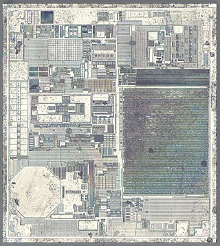
A carbon nanotube field-effect transistor (CNTFET) is a field-effect transistor that utilizes a single carbon nanotube (CNT) or an array of carbon nanotubes as the channel material, instead of bulk silicon, as in the traditional MOSFET structure. There have been major developments since CNTFETs were first demonstrated in 1998.

A nanogenerator is a compact device that converts mechanical or thermal energy into electricity, serving as an energy harvesting solution for small, wireless autonomous devices. It taps into ambient energy sources like solar, wind, thermal differentials, and kinetic energy, enabling power generation for applications such as wearable electronics and wireless sensor networks. Nanogenerators utilize ambient background energy readily available in the environment, such as temperature gradients from machinery operation, electromagnetic energy in urban areas, or even motion vibrations during activities like walking. This approach offers a means to power low-energy electronics without the need for conventional fuel sources.

<span class="mw-page-title-main">Nanoscale plasmonic motor</span>

A nanoscale plasmonic motor is a type of nanomotor, converting light energy to rotational motion at nanoscale. It is constructed from pieces of gold sheet in a gammadion shape, embedded within layers of silica. When irradiated with light from a laser, the gold pieces rotate. The functioning is explained by the quantum concept of the plasmon. This type of nanomotor is much smaller than other types, and its operation can be controlled by varying the frequency of the incident light.

<span class="mw-page-title-main">Supercapacitor</span> High-capacity electrochemical capacitor

A supercapacitor (SC), also called an ultracapacitor, is a high-capacity capacitor, with a capacitance value much higher than solid-state capacitors but with lower voltage limits. It bridges the gap between electrolytic capacitors and rechargeable batteries. It typically stores 10 to 100 times more energy per unit volume or mass than electrolytic capacitors, can accept and deliver charge much faster than batteries, and tolerates many more charge and discharge cycles than rechargeable batteries.

The history of electrovibration goes back to 1954. It was first discovered by accident and E. Mallinckrodt, A. L. Hughes and W. Sleator Jr. reported “... that dragging a dry finger over a conductive surface covered with a thin insulating layer and excited with a 110 V signal, created a characteristic rubbery feeling”. In their experiment, the finger and the metal surface create a capacitive setup. The attraction force created between the finger and the surface was too weak to perceive, but it generated a rubbery sensation when the finger was moving on the surface. This sensation was named "electrovibration" by the group. From around early 2010 Senseg and Disney Research are developing technology that could bring electrovibration to modern touchscreen devices.

This article provides information on the following six methods of producing electric power.

  1. Friction: Energy produced by rubbing two material together.
  2. Heat: Energy produced by heating the junction where two unlike metals are joined.
  3. Light: Energy produced by light being absorbed by photoelectric cells, or solar power.
  4. Chemical: Energy produced by chemical reaction in a voltaic cell, such as an electric battery.
  5. Pressure: Energy produced by compressing or decompressing specific crystals.
  6. Magnetism: Energy produced in a conductor that cuts or is cut by magnetic lines of force.

In nanotechnology, carbon nanotube interconnects refer to the proposed use of carbon nanotubes in the interconnects between the elements of an integrated circuit. Carbon nanotubes (CNTs) can be thought of as single atomic layer graphite sheets rolled up to form seamless cylinders. Depending on the direction on which they are rolled, CNTs can be semiconducting or metallic. Metallic carbon nanotubes have been identified as a possible interconnect material for the future technology generations and to replace copper interconnects. Electron transport can go over long nanotube lengths, 1 μm, enabling CNTs to carry very high currents (i.e. up to a current density of 109 A∙cm−2) with essentially no heating due to nearly one dimensional electronic structure. Despite the current saturation in CNTs at high fields, the mitigation of such effects is possible due to encapsulated nanowires.

In materials science, vertically aligned carbon nanotube arrays (VANTAs) are a unique microstructure consisting of carbon nanotubes oriented with their longitudinal axis perpendicular to a substrate surface. These VANTAs effectively preserve and often accentuate the unique anisotropic properties of individual carbon nanotubes and possess a morphology that may be precisely controlled. VANTAs are consequently widely useful in a range of current and potential device applications.

References

  1. "Nanosystems by K. Eric Drexler" . Retrieved 2009-11-29.
  2. "Nanosystems by K. Eric Drexler". Archived from the original on 2017-08-18. Retrieved 2009-11-29.
  3. "Models present a new view of nanoscale friction". Archived from the original on 2009-10-28. Retrieved 2009-11-15.
  4. Zhang, Xia-Hua; Ugo Tartaglino; Giuseppe E. Santoro; Erio Tosatti (2008). "Velocity plateaus and jumps in carbon nanotube sliding". Surface Science. 601 (18): 1–9. arXiv: 0707.0765 . Bibcode:2007SurSc.601.3693Z. doi:10.1016/j.susc.2007.05.034. S2CID   16861600.
  5. 1 2 3 4 Fennimore, A. M.; T.D. Yuzvinsky; Wei-Qiang Han; M. S. Fuhrer; J. Cumings; A. Zettl (2003). "Rotational actuators based on carbon nanotubes". Nature. 424 (6947): 408–410. Bibcode:2003Natur.424..408F. doi:10.1038/nature01823. PMID   12879064. S2CID   2200106.
  6. Fennimore, A. M.; T.D. Yuzvinsky; B. C. Regan; A. Zettl (2004). "Electrically Driven Vaporization of Multiwall Carbon Nanotubes for Rotary Bearing Creation". American Institute of Physics Conference Series. 723: 587–590. Bibcode:2004AIPC..723..587F. doi:10.1063/1.1812155.
  7. Yuzvinsky, T. D.; A. M. Fennimore; A Kis; A. Zettl (2006). "Controlled placement of highly aligned carbon nanotubes for the manufacture of arrays of nanoscale torsional actuators" (PDF). Nanotechnology. 17 (2): 434–437. Bibcode:2006Nanot..17..434Y. doi:10.1088/0957-4484/17/2/015. S2CID   37039716.
  8. Ebbesen, T. W.; Ajayan, P. M. (1992). "Large-scale synthesis of carbon nanotubes". Nature. 358 (6383): 220–222. Bibcode:1992Natur.358..220E. doi:10.1038/358220a0. S2CID   4270290.
  9. Dervishi, Enkeleda.; Li, Zhongrui; Xu, Yang; Saini, Viney; Biris, Alexandru R.; Lupu, Dan; Biris, Alexandru S (2009). "Carbon Nanotubes: Synthesis, Properties, and Applications". Particulate Science and Technology. 27 (2): 107–125. doi:10.1080/02726350902775962. S2CID   95718445.
  10. Collins, Philip G.; Arnold, Michael S.; Avouris, Phaedon. (2001). "Engineering Carbon Nanotubes and Nanotube Circuits Using Electrical Breakdown". Science. 292 (5517): 706–709. Bibcode:2001Sci...292..706C. CiteSeerX   10.1.1.474.7203 . doi:10.1126/science.1058782. PMID   11326094. S2CID   14479192.
  11. 1 2 3 4 5 6 7 8 Barreiro, Amelia; Ricardo Rurali; Eduardo R. Hernandez; Joel Moser; Thomas Pichler; Laszlo Forro; Adrian Bachtold (2008). "Subnanometer motion of cargoes driven by thermal gradients along carbon nanotubes". Science. 320 (5877): 775–778. Bibcode:2008Sci...320..775B. doi: 10.1126/science.1155559 . PMID   18403675. S2CID   6026906.
  12. 1 2 3 Bailey, S. W. D.; I. Amanatidis; C. J. Lambert (2008). "Carbon Nanotube Electron Windmills: A Novel Design for Nanomotors". Physical Review Letters. 100 (25): 256802. arXiv: 0806.1468 . Bibcode:2008PhRvL.100y6802B. doi:10.1103/PhysRevLett.100.256802. PMID   18643689. S2CID   19560027.