A broadcast domain is a logical division of a computer network, in which all nodes can reach each other by broadcast at the data link layer. A broadcast domain can be within the same LAN segment or it can be bridged to other LAN segments.
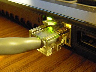
Ethernet is a family of wired computer networking technologies commonly used in local area networks (LAN), metropolitan area networks (MAN) and wide area networks (WAN). It was commercially introduced in 1980 and first standardized in 1983 as IEEE 802.3. Ethernet has since been refined to support higher bit rates, a greater number of nodes, and longer link distances, but retains much backward compatibility. Over time, Ethernet has largely replaced competing wired LAN technologies such as Token Ring, FDDI and ARCNET.
Network throughput refers to the rate of message delivery over a communication channel, such as Ethernet or packet radio, in a communication network. The data that these messages contain may be delivered over physical or logical links, or through network nodes. Throughput is usually measured in bits per second, and sometimes in data packets per second or data packets per time slot.
A network switch is networking hardware that connects devices on a computer network by using packet switching to receive and forward data to the destination device.

Carrier-sense multiple access with collision avoidance (CSMA/CA) in computer networking, is a network multiple access method in which carrier sensing is used, but nodes attempt to avoid collisions by beginning transmission only after the channel is sensed to be "idle". When they do transmit, nodes transmit their packet data in its entirety.
Carrier-sense multiple access with collision detection (CSMA/CD) is a medium access control (MAC) method used most notably in early Ethernet technology for local area networking. It uses carrier-sensing to defer transmissions until no other stations are transmitting. This is used in combination with collision detection in which a transmitting station detects collisions by sensing transmissions from other stations while it is transmitting a frame. When this collision condition is detected, the station stops transmitting that frame, transmits a jam signal, and then waits for a random time interval before trying to resend the frame.
Network topology is the arrangement of the elements of a communication network. Network topology can be used to define or describe the arrangement of various types of telecommunication networks, including command and control radio networks, industrial fieldbusses and computer networks.
Carrier-sense multiple access (CSMA) is a medium access control (MAC) protocol in which a node verifies the absence of other traffic before transmitting on a shared transmission medium, such as an electrical bus or a band of the electromagnetic spectrum.
In telecommunications and computer networks, a channel access method or multiple access method allows more than two terminals connected to the same transmission medium to transmit over it and to share its capacity. Examples of shared physical media are wireless networks, bus networks, ring networks and point-to-point links operating in half-duplex mode.
ALOHAnet, also known as the ALOHA System, or simply ALOHA, was a pioneering computer networking system developed at the University of Hawaii.
The data link layer, or layer 2, is the second layer of the seven-layer OSI model of computer networking. This layer is the protocol layer that transfers data between nodes on a network segment across the physical layer. The data link layer provides the functional and procedural means to transfer data between network entities and may also provide the means to detect and possibly correct errors that can occur in the physical layer.

A communication channel refers either to a physical transmission medium such as a wire, or to a logical connection over a multiplexed medium such as a radio channel in telecommunications and computer networking. A channel is used for information transfer of, for example, a digital bit stream, from one or several senders to one or several receivers. A channel has a certain capacity for transmitting information, often measured by its bandwidth in Hz or its data rate in bits per second.

In IEEE 802 LAN/MAN standards, the medium access control (MAC), also called media access control, is the layer that controls the hardware responsible for interaction with the wired or wireless transmission medium. The MAC sublayer and the logical link control (LLC) sublayer together make up the data link layer. The LLC provides flow control and multiplexing for the logical link, while the MAC provides flow control and multiplexing for the transmission medium.
A network segment is a portion of a computer network. The nature and extent of a segment depends on the nature of the network and the device or devices used to interconnect end stations.
In telecommunications, a point-to-point connection refers to a communications connection between two communication endpoints or nodes. An example is a telephone call, in which one telephone is connected with one other, and what is said by one caller can only be heard by the other. This is contrasted with a point-to-multipoint or broadcast connection, in which many nodes can receive information transmitted by one node. Other examples of point-to-point communications links are leased lines and microwave radio relay.
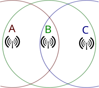
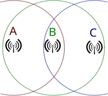
In wireless networking, the hidden node problem or hidden terminal problem occurs when a node can communicate with a wireless access point (AP), but cannot directly communicate with other nodes that are communicating with that AP. This leads to difficulties in medium access control sublayer since multiple nodes can send data packets to the AP simultaneously, which creates interference at the AP resulting in no packet getting through.
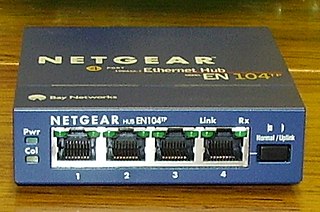
An Ethernet hub, active hub, network hub, repeater hub, multiport repeater, or simply hub is a network hardware device for connecting multiple Ethernet devices together and making them act as a single network segment. It has multiple input/output (I/O) ports, in which a signal introduced at the input of any port appears at the output of every port except the original incoming. A hub works at the physical layer. A repeater hub also participates in collision detection, forwarding a jam signal to all ports if it detects a collision. In addition to standard 8P8C ("RJ45") ports, some hubs may also come with a BNC or an Attachment Unit Interface (AUI) connector to allow connection to legacy 10BASE2 or 10BASE5 network segments.
A duplex communication system is a point-to-point system composed of two or more connected parties or devices that can communicate with one another in both directions. Duplex systems are employed in many communications networks, either to allow for simultaneous communication in both directions between two connected parties or to provide a reverse path for the monitoring and remote adjustment of equipment in the field. There are two types of duplex communication systems: full-duplex (FDX) and half-duplex (HDX).
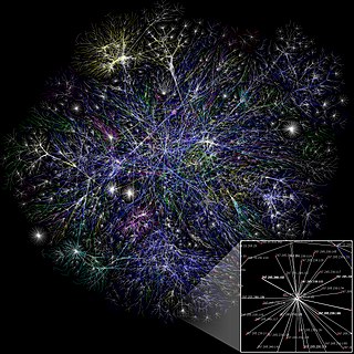
A computer network is a set of computers sharing resources located on or provided by network nodes. Computers use common communication protocols over digital interconnections to communicate with each other. These interconnections are made up of telecommunication network technologies based on physically wired, optical, and wireless radio-frequency methods that may be arranged in a variety of network topologies.
The 5-4-3 rule, also referred to as the IEEE way, is a design guideline for Ethernet computer networks covering the number of repeaters and segments on shared-medium Ethernet backbones in a tree topology. It means that in a collision domain there should be at most 5 segments tied together with 4 repeaters, with up to 3 mixing segments. Link segments can be 10BASE-T, 10BASE-FL or 10BASE-FB. This rule is also designated the 5-4-3-2-1 rule with there being two link segments and one collision domain.