
In telecommunications, RS-232 or Recommended Standard 232 is a standard originally introduced in 1960 for serial communication transmission of data. It formally defines signals connecting between a DTE such as a computer terminal, and a DCE, such as a modem. The standard defines the electrical characteristics and timing of signals, the meaning of signals, and the physical size and pinout of connectors. The current version of the standard is TIA-232-F Interface Between Data Terminal Equipment and Data Circuit-Terminating Equipment Employing Serial Binary Data Interchange, issued in 1997. The RS-232 standard had been commonly used in computer serial ports and is still widely used in industrial communication devices.

A universal asynchronous receiver-transmitter is a computer hardware device for asynchronous serial communication in which the data format and transmission speeds are configurable. It sends data bits one by one, from the least significant to the most significant, framed by start and stop bits so that precise timing is handled by the communication channel. The electric signaling levels are handled by a driver circuit external to the UART. Common signal levels are RS-232, RS-485, and raw TTL for short debugging links. Early teletypewriters used current loops.

On computers, a serial port is a serial communication interface through which information transfers in or out sequentially one bit at a time. This is in contrast to a parallel port, which communicates multiple bits simultaneously in parallel. Throughout most of the history of personal computers, data has been transferred through serial ports to devices such as modems, terminals, various peripherals, and directly between computers.
GeoPort is a serial data system used on some models of the Apple Macintosh that could be externally clocked to run at a 2 megabit per second data rate. GeoPort slightly modified the existing Mac serial port pins to allow the computer's internal DSP hardware or software to send data that, when passed to a digital-to-analog converter, emulated various devices such as modems and fax machines. GeoPort could be found on late-model 68K-based machines as well as many pre-USB Power Macintosh models and PiPPiN. Some later Macintosh models also included an internal GeoPort via an internal connector on the Communications Slot. Apple GeoPort technology is now obsolete, and modem support is typically offered through USB.
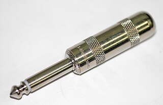
A phone connector, also known as phone jack, audio jack, headphone jack or jack plug, is a family of electrical connectors typically used for analog audio signals. A plug, the "male" connector, is inserted into the jack, the "female" connector.

Electronic test equipment is used to create signals and capture responses from electronic devices under test (DUTs). In this way, the proper operation of the DUT can be proven or faults in the device can be traced. Use of electronic test equipment is essential to any serious work on electronics systems.

DMX512 is a standard for digital communication networks that are commonly used to control lighting and effects. It was originally intended as a standardized method for controlling stage lighting dimmers, which, prior to DMX512, had employed various incompatible proprietary protocols. It quickly became the primary method for linking controllers to dimmers and special effects devices such as fog machines and intelligent lights.

A registered jack (RJ) is a standardized telecommunication network interface for connecting voice and data equipment to a service provided by a local exchange carrier or long distance carrier. Registration interfaces were first defined in the Universal Service Ordering Code (USOC) system of the Bell System in the United States for complying with the registration program for customer-supplied telephone equipment mandated by the Federal Communications Commission (FCC) in the 1970s. They were subsequently codified in title 47 of the Code of Federal Regulations Part 68. Registered jack connections began to see use after their invention in 1973 by Bell Labs. The specification includes physical construction, wiring, and signal semantics. Accordingly, registered jacks are primarily named by the letters RJ, followed by two digits that express the type. Additional letter suffixes indicate minor variations. For example, RJ11, RJ14, and RJ25 are the most commonly used interfaces for telephone connections for one-, two-, and three-line service, respectively. Although these standards are legal definitions in the United States, some interfaces are used worldwide.

RS-422, also known as TIA/EIA-422, is a technical standard originated by the Electronic Industries Alliance, first issued in 1975, that specifies electrical characteristics of a digital signaling circuit. It was meant to be the foundation of a suite of standards that would replace the older RS-232C standard with standards that offered much higher speed, better immunity from noise, and longer cable lengths. RS-422 systems can transmit data at rates as high as 10 Mbit/s, or may be sent on cables as long as 1,200 meters (3,900 ft) at lower rates. It is closely related to RS-423, which uses the same signaling systems but on a different wiring arrangement.
Serial Peripheral Interface (SPI) is a de facto standard for synchronous serial communication, used primarily in embedded systems for short-distance wired communication between integrated circuits.

The D-subminiature or D-sub is a common type of electrical connector. They are named for their characteristic D-shaped metal shield. When they were introduced, D-subs were among the smallest connectors used on computer systems.
The System Management Bus is a single-ended simple two-wire bus for the purpose of lightweight communication. Most commonly it is found in chipsets of computer motherboards for communication with the power source for ON/OFF instructions. The exact functionality and hardware interfaces vary with vendors.

Null modem is a communication method to directly connect two DTEs using an RS-232 serial cable. The name stems from the historical use of RS-232 cables to connect two teleprinter devices or two modems in order to communicate with one another; null modem communication refers to using a crossed-over RS-232 cable to connect the teleprinters directly to one another without the modems. It is also used to serially connect a computer to a printer, since both are DTE, and is known as a Printer Cable.
RS-485, also known as TIA-485(-A) or EIA-485, is a standard, originally introduced in 1983, defining the electrical characteristics of drivers and receivers for use in serial communications systems. Electrical signaling is balanced, and multipoint systems are supported. The standard is jointly published by the Telecommunications Industry Association and Electronic Industries Alliance (TIA/EIA). Digital communications networks implementing the standard can be used effectively over long distances and in electrically noisy environments. Multiple receivers may be connected to such a network in a linear, multidrop bus. These characteristics make RS-485 useful in industrial control systems and similar applications.

USB On-The-Go is a specification first used in late 2001 that allows USB devices, such as tablets or smartphones, to also act as a host, allowing other USB devices, such as USB flash drives, digital cameras, mouse or keyboards, to be attached to them. Use of USB OTG allows those devices to switch back and forth between the roles of host and device. A mobile phone may read from removable media as the host device, but present itself as a USB Mass Storage Device when connected to a host computer.

The PS/2 port is a 6-pin mini-DIN connector used for connecting keyboards and mice to a PC compatible computer system. Its name comes from the IBM Personal System/2 series of personal computers, with which it was introduced in 1987. The PS/2 mouse connector generally replaced the older DE-9 RS-232 "serial mouse" connector, while the PS/2 keyboard connector replaced the larger 5-pin/180° DIN connector used in the IBM PC/AT design. The PS/2 keyboard port is electrically and logically identical to the IBM AT keyboard port, differing only in the type of electrical connector used. The PS/2 platform introduced a second port with the same design as the keyboard port for use to connect a mouse; thus the PS/2-style keyboard and mouse interfaces are electrically similar and employ the same communication protocol. However, unlike the otherwise similar Apple Desktop Bus connector used by Apple, a given system's keyboard and mouse port may not be interchangeable since the two devices use different sets of commands and the device drivers generally are hard-coded to communicate with each device at the address of the port that is conventionally assigned to that device.

IEEE Standard 1355-1995, IEC 14575, or ISO 14575 is a data communications standard for Heterogeneous Interconnect (HIC).
A modular connector is a type of electrical connector for cords and cables of electronic devices and appliances, such as in computer networking, telecommunication equipment, and audio headsets.
RS-423, also known as TIA/EIA-423, is a technical standard originated by the Electronic Industries Alliance that specifies electrical characteristics of a digital signaling circuit. Although it was originally intended as a successor to RS-232C offering greater cable lengths, it is not widely used.
Assembly Line Diagnostic Link, Assembly Line Data Link, or ALDL is a proprietary on-board diagnostics system developed by General Motors before the standardization of OBD-2. It was previously called Assembly Line Communications Link or ALCL. The two terms are used interchangeably.