
The ionosphere is the ionized part of the upper atmosphere of Earth, from about 48 km (30 mi) to 965 km (600 mi) above sea level, a region that includes the thermosphere and parts of the mesosphere and exosphere. The ionosphere is ionized by solar radiation. It plays an important role in atmospheric electricity and forms the inner edge of the magnetosphere. It has practical importance because, among other functions, it influences radio propagation to distant places on Earth. It also affects GPS signals that travel through this layer.

In optics, the refractive index of an optical medium is a dimensionless number that gives the indication of the light bending ability of that medium.
In physics, refraction is the redirection of a wave as it passes from one medium to another. The redirection can be caused by the wave's change in speed or by a change in the medium. Refraction of light is the most commonly observed phenomenon, but other waves such as sound waves and water waves also experience refraction. How much a wave is refracted is determined by the change in wave speed and the initial direction of wave propagation relative to the direction of change in speed.

In physics, total internal reflection (TIR) is the phenomenon in which waves arriving at the interface (boundary) from one medium to another are not refracted into the second ("external") medium, but completely reflected back into the first ("internal") medium. It occurs when the second medium has a higher wave speed than the first, and the waves are incident at a sufficiently oblique angle on the interface. For example, the water-to-air surface in a typical fish tank, when viewed obliquely from below, reflects the underwater scene like a mirror with no loss of brightness (Fig. 1).
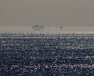
In telecommunications, an atmospheric duct is a horizontal layer in the lower atmosphere in which the vertical refractive index gradients are such that radio signals are guided or ducted, tend to follow the curvature of the Earth, and experience less attenuation in the ducts than they would if the ducts were not present. The duct acts as an atmospheric dielectric waveguide and limits the spread of the wavefront to only the horizontal dimension.

In optics, the numerical aperture (NA) of an optical system is a dimensionless number that characterizes the range of angles over which the system can accept or emit light. By incorporating index of refraction in its definition, NA has the property that it is constant for a beam as it goes from one material to another, provided there is no refractive power at the interface. The exact definition of the term varies slightly between different areas of optics. Numerical aperture is commonly used in microscopy to describe the acceptance cone of an objective, and in fiber optics, in which it describes the range of angles within which light that is incident on the fiber will be transmitted along it.
Path loss, or path attenuation, is the reduction in power density (attenuation) of an electromagnetic wave as it propagates through space. Path loss is a major component in the analysis and design of the link budget of a telecommunication system.
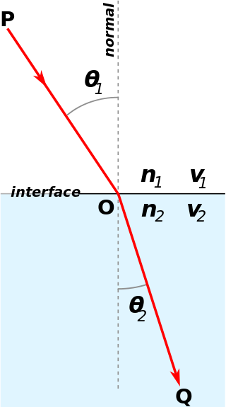
Snell's law is a formula used to describe the relationship between the angles of incidence and refraction, when referring to light or other waves passing through a boundary between two different isotropic media, such as water, glass, or air. In optics, the law is used in ray tracing to compute the angles of incidence or refraction, and in experimental optics to find the refractive index of a material. The law is also satisfied in meta-materials, which allow light to be bent "backward" at a negative angle of refraction with a negative refractive index.

Line-of-sight propagation is a characteristic of electromagnetic radiation or acoustic wave propagation which means waves travel in a direct path from the source to the receiver. Electromagnetic transmission includes light emissions traveling in a straight line. The rays or waves may be diffracted, refracted, reflected, or absorbed by the atmosphere and obstructions with material and generally cannot travel over the horizon or behind obstacles.
Radio propagation is the behavior of radio waves as they travel, or are propagated, from one point to another in vacuum, or into various parts of the atmosphere. As a form of electromagnetic radiation, like light waves, radio waves are affected by the phenomena of reflection, refraction, diffraction, absorption, polarization, and scattering. Understanding the effects of varying conditions on radio propagation has many practical applications, from choosing frequencies for amateur radio communications, international shortwave broadcasters, to designing reliable mobile telephone systems, to radio navigation, to operation of radar systems.
In astronomy, air mass or airmass is a measure of the amount of air along the line of sight when observing a star or other celestial source from below Earth's atmosphere. It is formulated as the integral of air density along the light ray.
Geometrical optics, or ray optics, is a model of optics that describes light propagation in terms of rays. The ray in geometrical optics is an abstraction useful for approximating the paths along which light propagates under certain circumstances.

An antireflective, antiglare or anti-reflection (AR) coating is a type of optical coating applied to the surface of lenses, other optical elements, and photovoltaic cells to reduce reflection. In typical imaging systems, this improves the efficiency since less light is lost due to reflection. In complex systems such as cameras, binoculars, telescopes, and microscopes the reduction in reflections also improves the contrast of the image by elimination of stray light. This is especially important in planetary astronomy. In other applications, the primary benefit is the elimination of the reflection itself, such as a coating on eyeglass lenses that makes the eyes of the wearer more visible to others, or a coating to reduce the glint from a covert viewer's binoculars or telescopic sight.

Atmospheric refraction is the deviation of light or other electromagnetic wave from a straight line as it passes through the atmosphere due to the variation in air density as a function of height. This refraction is due to the velocity of light through air decreasing with increased density. Atmospheric refraction near the ground produces mirages. Such refraction can also raise or lower, or stretch or shorten, the images of distant objects without involving mirages. Turbulent air can make distant objects appear to twinkle or shimmer. The term also applies to the refraction of sound. Atmospheric refraction is considered in measuring the position of both celestial and terrestrial objects.
Non-line-of-sight (NLOS) radio propagation occurs outside of the typical line-of-sight (LOS) between the transmitter and receiver, such as in ground reflections. Near-line-of-sight conditions refer to partial obstruction by a physical object present in the innermost Fresnel zone.
The beam propagation method (BPM) is an approximation technique for simulating the propagation of light in slowly varying optical waveguides. It is essentially the same as the so-called parabolic equation (PE) method in underwater acoustics. Both BPM and the PE were first introduced in the 1970s. When a wave propagates along a waveguide for a large distance, rigorous numerical simulation is difficult. The BPM relies on approximate differential equations which are also called the one-way models. These one-way models involve only a first order derivative in the variable z and they can be solved as "initial" value problem. The "initial" value problem does not involve time, rather it is for the spatial variable z.
The air mass coefficient defines the direct optical path length through the Earth's atmosphere, expressed as a ratio relative to the path length vertically upwards, i.e. at the zenith. The air mass coefficient can be used to help characterize the solar spectrum after solar radiation has traveled through the atmosphere.
This is an index to articles about terms used in discussion of radio propagation.
Cladding in optical fibers is one or more layers of materials of lower refractive index in intimate contact with a core material of higher refractive index. The cladding causes light to be confined to the core of the fiber by total internal reflection at the boundary between the core and cladding. Light propagation within the cladding is typically suppressed for most fibers. However, some fibers can support cladding modes in which light propagates through the cladding as well as the core. Depending upon the quantity of modes that are supported, they are referred to as multi-mode fibers and single-mode fibers. Improving transmission through fibers by applying a cladding was discovered in 1953 by Dutch scientist Bram van Heel.
Geometrical acoustics or ray acoustics is a branch of acoustics that studies propagation of sound on the basis of the concept of acoustic rays, defined as lines along which the acoustic energy is transported. This concept is similar to geometrical optics, or ray optics, that studies light propagation in terms of optical rays. Geometrical acoustics is an approximate theory, valid in the limiting case of very small wavelengths, or very high frequencies. The principal task of geometrical acoustics is to determine the trajectories of sound rays. The rays have the simplest form in a homogeneous medium, where they are straight lines. If the acoustic parameters of the medium are functions of spatial coordinates, the ray trajectories become curvilinear, describing sound reflection, refraction, possible focusing, etc. The equations of geometric acoustics have essentially the same form as those of geometric optics. The same laws of reflection and refraction hold for sound rays as for light rays. Geometrical acoustics does not take into account such important wave effects as diffraction. However, it provides a very good approximation when the wavelength is very small compared to the characteristic dimensions of inhomogeneous inclusions through which the sound propagates.


