Amplitude modulation (AM) is a modulation technique used in electronic communication, most commonly for transmitting messages with a radio wave. In amplitude modulation, the amplitude of the wave is varied in proportion to that of the message signal, such as an audio signal. This technique contrasts with angle modulation, in which either the frequency of the carrier wave is varied, as in frequency modulation, or its phase, as in phase modulation.
In electronics and telecommunications, modulation is the process of varying one or more properties of a periodic waveform, called the carrier signal, with a separate signal called the modulation signal that typically contains information to be transmitted. For example, the modulation signal might be an audio signal representing sound from a microphone, a video signal representing moving images from a video camera, or a digital signal representing a sequence of binary digits, a bitstream from a computer.
Quadrature amplitude modulation (QAM) is the name of a family of digital modulation methods and a related family of analog modulation methods widely used in modern telecommunications to transmit information. It conveys two analog message signals, or two digital bit streams, by changing (modulating) the amplitudes of two carrier waves, using the amplitude-shift keying (ASK) digital modulation scheme or amplitude modulation (AM) analog modulation scheme. The two carrier waves are of the same frequency and are out of phase with each other by 90°, a condition known as orthogonality or quadrature. The transmitted signal is created by adding the two carrier waves together. At the receiver, the two waves can be coherently separated (demodulated) because of their orthogonality. Another key property is that the modulations are low-frequency/low-bandwidth waveforms compared to the carrier frequency, which is known as the narrowband assumption.

In radio communications, single-sideband modulation (SSB) or single-sideband suppressed-carrier modulation (SSB-SC) is a type of modulation used to transmit information, such as an audio signal, by radio waves. A refinement of amplitude modulation, it uses transmitter power and bandwidth more efficiently. Amplitude modulation produces an output signal the bandwidth of which is twice the maximum frequency of the original baseband signal. Single-sideband modulation avoids this bandwidth increase, and the power wasted on a carrier, at the cost of increased device complexity and more difficult tuning at the receiver.

Delta modulation is an analog-to-digital and digital-to-analog signal conversion technique used for transmission of voice information where quality is not of primary importance. DM is the simplest form of differential pulse-code modulation (DPCM) where the difference between successive samples is encoded into n-bit data streams. In delta modulation, the transmitted data are reduced to a 1-bit data stream representing either up (↗) or down (↘). Its main features are:
In telecommunications, intersymbol interference (ISI) is a form of distortion of a signal in which one symbol interferes with subsequent symbols. This is an unwanted phenomenon as the previous symbols have a similar effect as noise, thus making the communication less reliable. The spreading of the pulse beyond its allotted time interval causes it to interfere with neighboring pulses. ISI is usually caused by multipath propagation or the inherent linear or non-linear frequency response of a communication channel causing successive symbols to blur together.
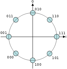
Phase-shift keying (PSK) is a digital modulation process which conveys data by changing (modulating) the phase of a constant frequency carrier wave. The modulation is accomplished by varying the sine and cosine inputs at a precise time. It is widely used for wireless LANs, RFID and Bluetooth communication.
Demodulation is extracting the original information-bearing signal from a carrier wave. A demodulator is an electronic circuit that is used to recover the information content from the modulated carrier wave. There are many types of modulation so there are many types of demodulators. The signal output from a demodulator may represent sound, images or binary data.
A satellite modem or satmodem is a modem used to establish data transfers using a communications satellite as a relay. A satellite modem's main function is to transform an input bitstream to a radio signal and vice versa.
A numerically controlled oscillator (NCO) is a digital signal generator which creates a synchronous, discrete-time, discrete-valued representation of a waveform, usually sinusoidal. NCOs are often used in conjunction with a digital-to-analog converter (DAC) at the output to create a direct digital synthesizer (DDS).

A vector signal analyzer is an instrument that measures the magnitude and phase of the input signal at a single frequency within the IF bandwidth of the instrument. The primary use is to make in-channel measurements, such as error vector magnitude, code domain power, and spectral flatness, on known signals.
Amplitude-shift keying (ASK) is a form of amplitude modulation that represents digital data as variations in the amplitude of a carrier wave. In an ASK system, a symbol, representing one or more bits, is sent by transmitting a fixed-amplitude carrier wave at a fixed frequency for a specific time duration. For example, if each symbol represents a single bit, then the carrier signal could be transmitted at nominal amplitude when the input value is 1, but transmitted at reduced amplitude or not at all when the input value is 0.
In digital modulation, minimum-shift keying (MSK) is a type of continuous-phase frequency-shift keying that was developed in the late 1950s by Collins Radio employees Melvin L. Doelz and Earl T. Heald. Similar to OQPSK, MSK is encoded with bits alternating between quadrature components, with the Q component delayed by half the symbol period.
In a digitally modulated signal or a line code, symbol rate, modulation rate or baud rate is the number of symbol changes, waveform changes, or signaling events across the transmission medium per unit of time. The symbol rate is measured in baud (Bd) or symbols per second. In the case of a line code, the symbol rate is the pulse rate in pulses per second. Each symbol can represent or convey one or several bits of data. The symbol rate is related to the gross bit rate, expressed in bits per second.

A sinusoid with modulation can be decomposed into, or synthesized from, two amplitude-modulated sinusoids that are in quadrature phase, i.e., with a phase offset of one-quarter cycle. All three sinusoids have the same center frequency. The two amplitude-modulated sinusoids are known as the in-phase (I) and quadrature (Q) components, which describes their relationships with the amplitude- and phase-modulated carrier.
The error vector magnitude or EVM is a measure used to quantify the performance of a digital radio transmitter or receiver. A signal sent by an ideal transmitter or received by a receiver would have all constellation points precisely at the ideal locations, however various imperfections in the implementation cause the actual constellation points to deviate from the ideal locations. Informally, EVM is a measure of how far the points are from the ideal locations.

In radio, a detector is a device or circuit that extracts information from a modulated radio frequency current or voltage. The term dates from the first three decades of radio (1888–1918). Unlike modern radio stations which transmit sound on an uninterrupted carrier wave, early radio stations transmitted information by radiotelegraphy. The transmitter was switched on and off to produce long or short periods of radio waves, spelling out text messages in Morse code. Therefore, early radio receivers could reproduce the Morse code "dots" and "dashes" by simply distinguishing between the presence or absence of a radio signal. The device that performed this function in the receiver circuit was called a detector. A variety of different detector devices, such as the coherer, electrolytic detector, magnetic detector and the crystal detector, were used during the wireless telegraphy era until superseded by vacuum tube technology.

A carrier recovery system is a circuit used to estimate and compensate for frequency and phase differences between a received signal's carrier wave and the receiver's local oscillator for the purpose of coherent demodulation.
The modulation error ratio or MER is a measure used to quantify the performance of a digital radio transmitter or receiver in a communications system using digital modulation. A signal sent by an ideal transmitter or received by a receiver would have all constellation points precisely at the ideal locations, however various imperfections in the implementation or signal path cause the actual constellation points to deviate from the ideal locations.
Constellation shaping is an energy efficiency enhancement method for digital signal modulation that improves upon amplitude and phase-shift keying (APSK) and conventional quadrature amplitude modulation (QAM) by modifying the continuous uniform distribution of the data symbols to match the channel. In a channel corrupted by an additive white Gaussian noise (AWGN), this implies transmitting low-energy signals more frequently than high-energy signals with the target to approach a Gaussian distribution of the transmission power.