
Analog television is the original television technology that uses analog signals to transmit video and audio. In an analog television broadcast, the brightness, colors and sound are represented by amplitude, phase and frequency of an analog signal.
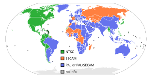
NTSC is the first American standard for analog television, published in 1941. In 1961, it was assigned the designation System M. It is also known as EIA standard.

Interlaced video is a technique for doubling the perceived frame rate of a video display without consuming extra bandwidth. The interlaced signal contains two fields of a video frame captured consecutively. This enhances motion perception to the viewer, and reduces flicker by taking advantage of the phi phenomenon.

Digital Visual Interface (DVI) is a video display interface developed by the Digital Display Working Group (DDWG). The digital interface is used to connect a video source, such as a video display controller, to a display device, such as a computer monitor. It was developed with the intention of creating an industry standard for the transfer of uncompressed digital video content.

VESA, formally known as Video Electronics Standards Association, is an American technical standards organization for computer display standards. The organization was incorporated in California in July 1989 and has its office in San Jose. It claims a membership of over 300 companies.

Video Graphics Array (VGA) is a video display controller and accompanying de facto graphics standard, first introduced with the IBM PS/2 line of computers in 1987, which became ubiquitous in the IBM PC compatible industry within three years. The term can now refer to the computer display standard, the 15-pin D-subminiature VGA connector, or the 640 × 480 resolution characteristic of the VGA hardware.

Chroma subsampling is the practice of encoding images by implementing less resolution for chroma information than for luma information, taking advantage of the human visual system's lower acuity for color differences than for luminance.
Extended Display Identification Data (EDID) and Enhanced EDID (E-EDID) are metadata formats for display devices to describe their capabilities to a video source. The data format is defined by a standard published by the Video Electronics Standards Association (VESA).

In a raster scan display, the vertical blanking interval (VBI), also known as the vertical interval or VBLANK, is the time between the end of the final visible line of a frame or field and the beginning of the first visible line of the next frame or field. It is present in analog television, VGA, DVI and other signals.
The refresh rate, also known as vertical refresh rate or vertical scan rate in reference to terminology originating with the cathode-ray tubes (CRTs), is the number of times per second that a raster-based display device displays a new image. This is independent from frame rate, which describes how many images are stored or generated every second by the device driving the display. On CRT displays, higher refresh rates produce less flickering, thereby reducing eye strain. In other technologies such as liquid-crystal displays, the refresh rate affects only how often the image can potentially be updated.

High-Definition Multimedia Interface (HDMI) is a proprietary audio/video interface for transmitting uncompressed video data and compressed or uncompressed digital audio data from an HDMI-compliant source device, such as a display controller, to a compatible computer monitor, video projector, digital television, or digital audio device. HDMI is a digital replacement for analog video standards.
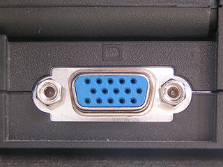
The Video Graphics Array (VGA) connector is a standard connector used for computer video output. Originating with the 1987 IBM PS/2 and its VGA graphics system, the 15-pin connector went on to become ubiquitous on PCs, as well as many monitors, projectors and high-definition television sets.
HD-MAC was a broadcast television standard proposed by the European Commission in 1986, as part of Eureka 95 project. It belongs to the MAC - Multiplexed Analogue Components standard family. It is an early attempt by the EEC to provide High-definition television (HDTV) in Europe. It is a complex mix of analogue signal, multiplexed with digital sound, and assistance data for decoding (DATV). The video signal was encoded with a modified D2-MAC encoder.
Overscan is a behaviour in certain television sets, in which part of the input picture is cut off by the visible bounds of the screen. It exists because cathode-ray tube (CRT) television sets from the 1930s to the early 2000s were highly variable in how the video image was positioned within the borders of the screen. It then became common practice to have video signals with black edges around the picture, which the television was meant to discard in this way.

DisplayPort (DP) is a digital display interface developed by a consortium of PC and chip manufacturers and standardized by the Video Electronics Standards Association (VESA). It is primarily used to connect a video source to a display device such as a computer monitor. It can also carry audio, USB, and other forms of data.
A multiple-sync (multisync) monitor, also known as a multiscan or multimode monitor, is a raster-scan analog video monitor that can properly synchronise with multiple horizontal and vertical scan rates. In contrast, fixed frequency monitors can only synchronise with a specific set of scan rates. They are generally used for computer displays, but sometimes for television, and the terminology is mostly applied to CRT displays although the concept applies to other technologies.

An oscilloscope is a type of electronic test instrument that graphically displays varying voltages of one or more signals as a function of time. Their main purpose is capturing information on electrical signals for debugging, analysis, or characterization. The displayed waveform can then be analyzed for properties such as amplitude, frequency, rise time, time interval, distortion, and others. Originally, calculation of these values required manually measuring the waveform against the scales built into the screen of the instrument. Modern digital instruments may calculate and display these properties directly.
Generalized Timing Formula is a standard by VESA which defines exact parameters of the component video signal for analogue VGA display interface.
DisplayID is a VESA standard for metadata describing display device capabilities to the video source. It is designed to replace E-EDID standard and EDID structure v1.4.
A modeline is a configuration line in xorg.conf or the XFree86 configuration file (XF86Config) that provides information to the display server about a connected computer monitor or television and how to drive it at a specified display resolution. The Modeline is based on the Generalized Timing Formula or the Coordinated Video Timings standards produced by VESA.