
Radar is a radiolocation system that uses radio waves to determine the distance (ranging), angle (azimuth), and radial velocity of objects relative to the site. It is used to detect and track aircraft, ships, spacecraft, guided missiles, motor vehicles, map weather formations, and terrain. A radar system consists of a transmitter producing electromagnetic waves in the radio or microwaves domain, a transmitting antenna, a receiving antenna and a receiver and processor to determine properties of the objects. Radio waves from the transmitter reflect off the objects and return to the receiver, giving information about the objects' locations and speeds.

Synthetic-aperture radar (SAR) is a form of radar that is used to create two-dimensional images or three-dimensional reconstructions of objects, such as landscapes. SAR uses the motion of the radar antenna over a target region to provide finer spatial resolution than conventional stationary beam-scanning radars. SAR is typically mounted on a moving platform, such as an aircraft or spacecraft, and has its origins in an advanced form of side looking airborne radar (SLAR). The distance the SAR device travels over a target during the period when the target scene is illuminated creates the large synthetic antenna aperture. Typically, the larger the aperture, the higher the image resolution will be, regardless of whether the aperture is physical or synthetic – this allows SAR to create high-resolution images with comparatively small physical antennas. For a fixed antenna size and orientation, objects which are further away remain illuminated longer – therefore SAR has the property of creating larger synthetic apertures for more distant objects, which results in a consistent spatial resolution over a range of viewing distances.
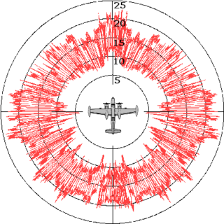
Radar cross-section (RCS), denoted σ, also called radar signature, is a measure of how detectable an object is by radar. A larger RCS indicates that an object is more easily detected.

H2S was the first airborne, ground scanning radar system. It was developed for the Royal Air Force's Bomber Command during World War II to identify targets on the ground for night and all-weather bombing. This allowed attacks outside the range of the various radio navigation aids like Gee or Oboe, which were limited to about 350 kilometres (220 mi) of range from various base stations. It was also widely used as a general navigation system, allowing landmarks to be identified at long range.
A pulse-Doppler radar is a radar system that determines the range to a target using pulse-timing techniques, and uses the Doppler effect of the returned signal to determine the target object's velocity. It combines the features of pulse radars and continuous-wave radars, which were formerly separate due to the complexity of the electronics.

Continuous-wave radar is a type of radar system where a known stable frequency continuous wave radio energy is transmitted and then received from any reflecting objects. Individual objects can be detected using the Doppler effect, which causes the received signal to have a different frequency from the transmitted signal, allowing it to be detected by filtering out the transmitted frequency.
A low-probability-of-intercept radar (LPIR) is a radar employing measures to avoid detection by passive radar detection equipment while it is searching for a target or engaged in target tracking. This characteristic is desirable in a radar because it allows finding and tracking an opponent without alerting them to the radar's presence. This also protects the radar installation from anti-radiation missiles (ARMs).
Radar jamming and deception is a form of electronic countermeasures that intentionally sends out radio frequency signals to interfere with the operation of radar by saturating its receiver with noise or false information. Concepts that blanket the radar with signals so its display cannot be read are normally known as jamming, while systems that produce confusing or contradictory signals are known as deception, but it is also common for all such systems to be referred to as jamming.

Terrain-following radar (TFR) is a military aerospace technology that allows a very-low-flying aircraft to automatically maintain a relatively constant altitude above ground level and therefore make detection by enemy radar more difficult. It is sometimes referred to as ground hugging or terrain hugging flight. The term nap-of-the-earth flight may also apply but is more commonly used in relation to low-flying military helicopters, which typically do not use terrain-following radar.

A radar altimeter (RA), also called a radio altimeter (RALT), electronic altimeter, reflection altimeter, or low-range radio altimeter (LRRA), measures altitude above the terrain presently beneath an aircraft or spacecraft by timing how long it takes a beam of radio waves to travel to ground, reflect, and return to the craft. This type of altimeter provides the distance between the antenna and the ground directly below it, in contrast to a barometric altimeter which provides the distance above a defined vertical datum, usually mean sea level.
Monopulse radar is a radar system that uses additional encoding of the radio signal to provide accurate directional information. The name refers to its ability to extract range and direction from a single signal pulse.
Fluctuation loss is an effect seen in radar systems as the target object moves or changes its orientation relative to the radar system. It was extensively studied during the 1950s by Peter Swerling, who introduced the Swerling models to allow the effect to be simulated. For this reason, it is sometimes known as Swerling loss or similar names.
In radar systems, the blip-to-scan ratio, or blip/scan, is the ratio of the number of times a target appears on a radar display to the number of times it theoretically could be displayed. Alternately it can be defined as the ratio of the number of scans in which an accurate return is received to the total number of scans.
Pulse-Doppler signal processing is a radar and CEUS performance enhancement strategy that allows small high-speed objects to be detected in close proximity to large slow moving objects. Detection improvements on the order of 1,000,000:1 are common. Small fast moving objects can be identified close to terrain, near the sea surface, and inside storms.
Radar envelope is a critical Measure of Performance (MOP) identified in the Test and Evaluation Master Plan (TEMP). This is the volume of space where a radar system is required to reliably detect an object with a specific size and speed. This is one of the requirements that must be evaluated as part of the acceptance testing process.

The radar horizon is a critical area of performance for aircraft detection systems that is defined by the distance at which the radar beam rises enough above the Earth's surface to make detection of a target at the lowest level possible. It is associated with the low elevation region of performance, and its geometry depends on terrain, radar height, and signal processing. This is associated with the notions of radar shadow, the clutter zone, and the clear zone.

The TRML is a family of air defense radars first developed by Telefunken and currently produced by Hensoldt. It is a development of the earlier TRMS.

A primary radar or primary surveillance radar (PSR) is a conventional radar sensor that illuminates a large portion of space with an electromagnetic wave and receives back the reflected waves from targets within that space. The term thus refers to a radar system used to detect and localize potentially non-cooperative targets. It is specific to the field of air traffic control where it is opposed to the secondary radar which receives additional information from the target's transponder.

AIRPASS was a British airborne interception radar and fire-control radar system developed by Ferranti. It was the world's first airborne monopulse radar system and fed data to the world's first head-up display. The name is an acronym for "Airborne Interception Radar and Pilot's Attack Sight System". In the Royal Air Force (RAF) it was given the official name Radar, Airborne Interception, Mark 23, normally shortened to AI.23. AIRPASS was used on the English Electric Lightning throughout its lifetime.

The AMES Type 82, also widely known by its rainbow codename Orange Yeoman, was an S-band 3D radar built by the Marconi Company and used by the Royal Air Force (RAF), initially for tactical control and later for air traffic control (ATC).
