Dielectric absorption is the name given to the effect by which a previously charged capacitor discharges incompletely when discharged, even over many seconds for some materials. Although an ideal capacitor would remain at zero volts after being discharged, real capacitors will develop a small voltage from time-delayed dipole discharging,[1] a phenomenon that is also called dielectric relaxation, "soakage", or "battery action". For some dielectrics, such as a couple of polymer films, the resulting voltage may be near .02% of the original voltage, but it can be as much as 15% for electrolytic capacitors. The voltage at the terminals generated by the dielectric absorption may possibly cause problems in the function of an electronic circuit or can be a safety risk to personnel. In order to prevent shocks, high-voltage or large electrolytic capacitors are often stored or shipped with shorting wires that need to be removed before they are used and/or permanently connected bleeder resistors. When disconnected at one or both ends, DC high-voltage cables can also "recharge themselves" to dangerous voltages.
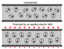
The random orientations of molecular dipoles in a dielectric are aligned under the influence of an electric field by applying a voltage to the electrodes.Circuit model for explaining a time-delayed voltage build-up by parallel RC-timers
Charging a capacitor (applying a voltage between the capacitor plates) causes an electric field to be applied to the dielectric between the electrodes. This field exerts a torque on the molecular dipoles, causing the directions of the dipole moments to align with the field direction. This change in the molecular dipoles is called oriented polarization and also causes heat to be generated, resulting in dielectric losses (see dissipation factor). The time of the dipoles orientation does not follow the electric field synchronously, but is delayed by a time constant that depends on the material. This delay corresponds to a hysteresis response of the polarization to the external field.
When the capacitor is discharged, the strength of the electric field decreases and the common orientation of the molecular dipoles returns to an undirected state in a process of relaxation. Due to the hysteresis, at the zero point of the electric field, a material-dependent number of molecular dipoles still remain polarized along the field direction without a measurable voltage appearing at the terminals of the capacitor. This is the electrostatic analog of magnetic remanence. The oriented dipoles will be discharged spontaneously over time and the voltage at the electrodes of the capacitor will decay exponentially.[2] The complete discharge time of all dipoles can be days to weeks depending on the material. This "reloaded" voltage can be retained for months, even in electrolytic capacitors, caused by the high insulation resistance in common modern capacitor dielectrics. The discharge of a capacitor and the subsequent partial recharging can be repeated several times.
Measurement
Dielectric absorption is a property which has been long known. Its value can be measured in accordance with the IEC/EN 60384-1 standard. The capacitor shall be charged at the DC voltage rating for 60 minutes. Then the capacitor shall be disconnected from the power source and shall be discharged for 10s. The voltage regained on the capacitor terminals (recovery voltage) within 15 minutes is the dielectric absorption voltage. The size of the dielectric absorption voltage is specified in relation to the applied voltage in percent and depends on the dielectric material. It is specified by many manufacturers in the data sheets.[3][4][5][6][7]
The voltage at the terminals generated by the dielectric absorption may possibly cause problems in the function of an electronic circuit. For sensitive analog circuits such as sample and hold circuits, integrators, charge amplifiers or high-quality audio circuits, Class-1 ceramic or polypropylene capacitors instead of Class-2 ceramic capacitors, polyester film capacitors or electrolytic capacitors are used.[11] For most electronic circuits, particularly filtering applications, the small dielectric absorption voltage has no influence on the proper electrical function of the circuit. For aluminum electrolytic capacitors with non-solid electrolyte which are not built into a circuit, the dielectric absorption voltage generated can be a personnel safety risk.[12] The voltage can be quite substantial, for example 50V for 400V electrolytic capacitors, and can cause damages to semiconductor devices, or cause sparks during installation in the circuit. Larger aluminum electrolytic capacitors and high-voltage power capacitors are transported and delivered short-circuited to dissipate this unwanted and possibly dangerous energy.
Another effect of dielectric absorption is sometimes described as "soakage". This manifests as a component of leakage current and it contributes to the loss factor of the capacitor. This effect has been known of only recently:[failed verification] it is now a proportionately greater part of leakage current due to the significantly improved properties of modern capacitors.[9]
Dielectric absorption was first discovered in Leyden jars and telegraph cables, and it was already a well-known phenomenon in the late 19th century. Once known as "electric absorption", satisfactory explanations of its physical mechanism was lacking at that time. A description appeared in James Clerk Maxwell's 1873 book A Treatise on Electricity and Magnetism, in which he derived its physical model, but it was only applicable to an inhomogeneous dielectric material with multiple layers.[13][14]
↑ WIMA, Characteristics of Metallized film capacitors in Comparison with Other Dielectrics "WIMA". Archived from the original on 2012-11-05. Retrieved 2012-12-14.
↑ Maxwell, James (1873). "Chapter X. Conduction in Dielectrics". A Treatise on Electricity and Magnetism. Clarendon Press. p.376. In a condenser of this kind, first charged in any way, next discharged through a wire of small resistance, and then insulated, no new electrification will appear. In most actual condensers, however, we find that after discharge and insulation a new charge is gradually developed, of the same kind as the original charge, but inferior in intensity. This is called the residual charge. To account for it we must admit that the constitution of the dielectric medium is different from that which we have just described. We shall find, however, that a medium formed of a conglomeration of small pieces of different simple media would possess this property.
This page is based on this Wikipedia article Text is available under the CC BY-SA 4.0 license; additional terms may apply. Images, videos and audio are available under their respective licenses.