
Microwave is a form of electromagnetic radiation with wavelengths shorter than other radio waves but longer than infrared waves. Its wavelength ranges from about one meter to one millimeter, corresponding to frequencies between 300 MHz and 300 GHz, broadly construed. A more common definition in radio-frequency engineering is the range between 1 and 100 GHz, or between 1 and 3000 GHz . The prefix micro- in microwave is not meant to suggest a wavelength in the micrometer range; rather, it indicates that microwaves are small, compared to the radio waves used in prior radio technology.
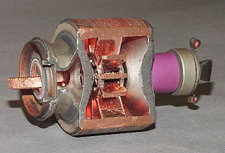
The cavity magnetron is a high-power vacuum tube used in early radar systems and subsequently in microwave ovens and in linear particle accelerators. A cavity magnetron generates microwaves using the interaction of a stream of electrons with a magnetic field, while moving past a series of cavity resonators, which are small, open cavities in a metal block. Electrons pass by the cavities and cause microwaves to oscillate within, similar to the functioning of a whistle producing a tone when excited by an air stream blown past its opening. The resonant frequency of the arrangement is determined by the cavities' physical dimensions. Unlike other vacuum tubes, such as a klystron or a traveling-wave tube (TWT), the magnetron cannot function as an amplifier for increasing the intensity of an applied microwave signal; the magnetron serves solely as an electronic oscillator generating a microwave signal from direct current electricity supplied to the vacuum tube.

A waveguide is a structure that guides waves by restricting the transmission of energy to one direction. Common types of waveguides include acoustic waveguides which direct sound, optical waveguides which direct light, and radio-frequency waveguides which direct electromagnetic waves other than light like radio waves.
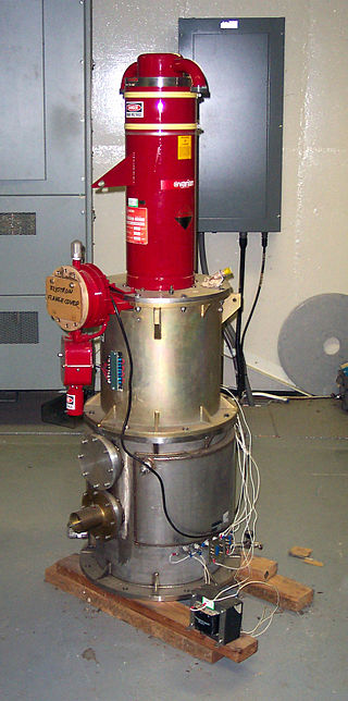
A klystron is a specialized linear-beam vacuum tube, invented in 1937 by American electrical engineers Russell and Sigurd Varian, which is used as an amplifier for high radio frequencies, from UHF up into the microwave range. Low-power klystrons are used as oscillators in terrestrial microwave relay communications links, while high-power klystrons are used as output tubes in UHF television transmitters, satellite communication, radar transmitters, and to generate the drive power for modern particle accelerators.
A resonator is a device or system that exhibits resonance or resonant behavior. That is, it naturally oscillates with greater amplitude at some frequencies, called resonant frequencies, than at other frequencies. The oscillations in a resonator can be either electromagnetic or mechanical. Resonators are used to either generate waves of specific frequencies or to select specific frequencies from a signal. Musical instruments use acoustic resonators that produce sound waves of specific tones. Another example is quartz crystals used in electronic devices such as radio transmitters and quartz watches to produce oscillations of very precise frequency.
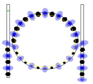
An optical ring resonator is a set of waveguides in which at least one is a closed loop coupled to some sort of light input and output. The concepts behind optical ring resonators are the same as those behind whispering galleries except that they use light and obey the properties behind constructive interference and total internal reflection. When light of the resonant wavelength is passed through the loop from the input waveguide, the light builds up in intensity over multiple round-trips owing to constructive interference and is output to the output bus waveguide which serves as a detector waveguide. Because only a select few wavelengths will be at resonance within the loop, the optical ring resonator functions as a filter. Additionally, as implied earlier, two or more ring waveguides can be coupled to each other to form an add/drop optical filter.

A Gunn diode, also known as a transferred electron device (TED), is a form of diode, a two-terminal semiconductor electronic component, with negative differential resistance, used in high-frequency electronics. It is based on the "Gunn effect" discovered in 1962 by physicist J. B. Gunn. Its main uses are in electronic oscillators to generate microwaves, in applications such as radar speed guns, microwave relay data link transmitters, and automatic door openers.
A Goubau line or Sommerfeld–Goubau line, or G-line for short, is a single-wire transmission line used to conduct radio waves at UHF and microwave frequencies. The dielectric coated transmission line was invented by F. Harms in 1907 and George J. E. Goubau in 1950, based on work on surface waves on wires from 1899 by Arnold Sommerfeld. It is used as a feedline at UHF to link high frequency transmitters and receivers to their antennas, and in scientific research.

A backward wave oscillator (BWO), also called carcinotron or backward wave tube, is a vacuum tube that is used to generate microwaves up to the terahertz range. Belonging to the traveling-wave tube family, it is an oscillator with a wide electronic tuning range.

In radio-frequency engineering and communications engineering, a waveguide is a hollow metal pipe used to carry radio waves. This type of waveguide is used as a transmission line mostly at microwave frequencies, for such purposes as connecting microwave transmitters and receivers to their antennas, in equipment such as microwave ovens, radar sets, satellite communications, and microwave radio links.
A dielectric resonator antenna (DRA) is a radio antenna mostly used at microwave frequencies and higher, that consists of a block of ceramic material of various shapes, the dielectric resonator, mounted on a metal surface, a ground plane. Radio waves are introduced into the inside of the resonator material from the transmitter circuit and bounce back and forth between the resonator walls, forming standing waves. The walls of the resonator are partially transparent to radio waves, allowing the radio power to radiate into space.
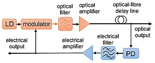
In optoelectronics, an opto-electronic oscillator (OEO) is a circuit that produces a repetitive electronic sine wave and/or modulated optical continuous wave signals.

A microwave cavity or radio frequency cavity is a special type of resonator, consisting of a closed metal structure that confines electromagnetic fields in the microwave or RF region of the spectrum. The structure is either hollow or filled with dielectric material. The microwaves bounce back and forth between the walls of the cavity. At the cavity's resonant frequencies they reinforce to form standing waves in the cavity. Therefore, the cavity functions similarly to an organ pipe or sound box in a musical instrument, oscillating preferentially at a series of frequencies, its resonant frequencies. Thus it can act as a bandpass filter, allowing microwaves of a particular frequency to pass while blocking microwaves at nearby frequencies.

A waveguide filter is an electronic filter constructed with waveguide technology. Waveguides are hollow metal conduits inside which an electromagnetic wave may be transmitted. Filters are devices used to allow signals at some frequencies to pass, while others are rejected. Filters are a basic component of electronic engineering designs and have numerous applications. These include selection of signals and limitation of noise. Waveguide filters are most useful in the microwave band of frequencies, where they are a convenient size and have low loss. Examples of microwave filter use are found in satellite communications, telephone networks, and television broadcasting.

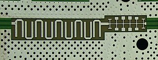
A substrate-integrated waveguide (SIW) is a synthetic rectangular electromagnetic waveguide formed in a dielectric substrate by densely arraying metallized posts or via holes that connect the upper and lower metal plates of the substrate. The waveguide can be easily fabricated with low-cost mass-production using through-hole techniques, where the post walls consists of via fences. SIW is known to have similar guided wave and mode characteristics to conventional rectangular waveguide with equivalent guide wavelength.
In mathematics and electronics, cavity perturbation theory describes methods for derivation of perturbation formulae for performance changes of a cavity resonator.
Circuit quantum electrodynamics provides a means of studying the fundamental interaction between light and matter. As in the field of cavity quantum electrodynamics, a single photon within a single mode cavity coherently couples to a quantum object (atom). In contrast to cavity QED, the photon is stored in a one-dimensional on-chip resonator and the quantum object is no natural atom but an artificial one. These artificial atoms usually are mesoscopic devices which exhibit an atom-like energy spectrum. The field of circuit QED is a prominent example for quantum information processing and a promising candidate for future quantum computation.
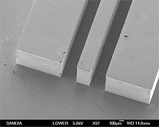
Planar transmission lines are transmission lines with conductors, or in some cases dielectric (insulating) strips, that are flat, ribbon-shaped lines. They are used to interconnect components on printed circuits and integrated circuits working at microwave frequencies because the planar type fits in well with the manufacturing methods for these components. Transmission lines are more than simply interconnections. With simple interconnections, the propagation of the electromagnetic wave along the wire is fast enough to be considered instantaneous, and the voltages at each end of the wire can be considered identical. If the wire is longer than a large fraction of a wavelength, these assumptions are no longer true and transmission line theory must be used instead. With transmission lines, the geometry of the line is precisely controlled so that its electrical behaviour is highly predictable. At lower frequencies, these considerations are only necessary for the cables connecting different pieces of equipment, but at microwave frequencies the distance at which transmission line theory becomes necessary is measured in millimetres. Hence, transmission lines are needed within circuits.
Coplanar waveguide is a type of electrical planar transmission line which can be fabricated using printed circuit board technology, and is used to convey microwave-frequency signals. On a smaller scale, coplanar waveguide transmission lines are also built into monolithic microwave integrated circuits.

Distributed-element circuits are electrical circuits composed of lengths of transmission lines or other distributed components. These circuits perform the same functions as conventional circuits composed of passive components, such as capacitors, inductors, and transformers. They are used mostly at microwave frequencies, where conventional components are difficult to implement.


