Diode bridge

Last updated

Diode bridge
Brueckengleichrichter IMGP5380.jpg
Diode bridge in various packages
Type Semiconductor
Invented Karol Pollak in 1895
Electronic symbol
Diode bridge.svg
2 alternating-current (AC) inputs converted into 2 direct-current (DC) outputs
A hand-made diode bridge. The silver band on the diodes indicates the cathode side of the diode. Diode bridge Diodovy mostik.jpg
A hand-made diode bridge. The silver band on the diodes indicates the cathode side of the diode.

A diode bridge is a bridge rectifier circuit of four diodes that is used in the process of converting alternating current (AC) from the input terminals to direct current (DC, i.e. fixed polarity) on the output terminals. Its function is to convert the negative voltage portions of the AC waveform to positive voltage, after which a low-pass filter can be used to smooth the result into DC. [1] :2

Contents

When used in its most common application, for conversion of an alternating-current (AC) input into a direct-current (DC) output, it is known as a bridge rectifier. A bridge rectifier provides full-wave rectification from a two-wire AC input, resulting in lower cost and weight as compared to a rectifier with a three-wire input from a transformer with a center-tapped secondary winding. [2]

Prior to the availability of integrated circuits, a bridge rectifier was constructed from separate diodes. Since about 1950, a single four-terminal component containing the four diodes connected in a bridge configuration has been available and is now available with various voltage and current ratings.

Diodes are also used in bridge topologies along with capacitors as voltage multipliers.

History

The diode bridge circuit was invented by Karol Pollak and patented in December 1895 in Great Britain [3] and in January 1896 in Germany. [4] [5] In 1897, Leo Graetz independently invented and published a similar circuit. [6] [7] Today the circuit is sometimes referred to as a "Graetz circuit" or "Graetz bridge". [8]

Current flow

According to the conventional model of current flow, originally established by Benjamin Franklin and still followed by most engineers today [9] ), current flows through electrical conductors from the positive to the negative pole (defined as positive flow). In actuality, free electrons in a conductor nearly always flow from the negative to the positive pole. In the vast majority of applications, however, the actual direction of current flow is irrelevant. Therefore, in the discussion below the conventional model is retained.

The fundamental characteristic of a diode is that current can flow only one way through it, which is defined as the forward direction. A diode bridge uses diodes as series components to allow current to pass in the forward direction during the positive part of the AC cycle and as shunt components to redirect current flowing in the reverse direction during the negative part of the AC cycle to the opposite rails.

Rectifier

In the diagrams below, when the input connected to the left corner of the diamond is positive, and the input connected to the right corner is negative, current flows from the upper supply terminal to the right along the red (positive) path to the output and returns to the lower supply terminal through the blue (negative) path.

Diode bridge alt 1.svg

When the input connected to the left corner is negative, and the input connected to the right corner is positive, current flows from the lower supply terminal to the right along the red (positive) path to the output and returns to the upper supply terminal through the blue (negative) path. [10]

Diode bridge alt 2.svg

Diodebridge-eng.gif

In each case, the upper right output remains positive, [11] and lower right output negative. Since this is true whether the input is AC or DC, this circuit not only produces a DC output from an AC input, it can also provide reverse-polarity protection; that is, it permits normal functioning of DC-powered equipment when batteries have been installed backwards, or when the leads from a DC power source have been reversed, and protects the equipment from potential damage caused by reverse polarity. [12]

Alternatives to the diode-bridge full-wave rectifiers are the center-tapped transformer and double-diode rectifier, and voltage doubler rectifier using two diodes and two capacitors in a bridge topology.

AC, half-wave and full-wave rectified signals Rectification.svg
AC, half-wave and full-wave rectified signals

Smoothing circuits

With AC input, the output of a diode bridge (called a full-wave rectifier for this purpose; there is also half-wave rectification, which does not use a diode bridge) is polarized pulsating non-sinusoidal voltage of the same amplitude but twice the frequency of the input. It may be considered as DC voltage upon which is superimposed a very large ripple voltage. This kind of electric power is not very usable, because ripple is dissipated as waste heat in DC circuit components and may cause noise or distortion during circuit operation. So nearly all rectifiers are followed by a series of bandpass or bandstop filters and/or a voltage regulator to convert most or all of the ripple voltage into a smoother and possibly higher DC output. A filter may be as simple as a single sufficiently large capacitor or choke, but most power-supply filters have multiple alternating series and shunt components. When the ripple voltage rises, reactive power is stored in the filter components, reducing the voltage; when the ripple voltage falls, reactive power is discharged from the filter components, raising the voltage. The final stage of rectification may consist of a zener diode-based voltage regulator, which almost completely eliminates any residual ripple.

Polyphase diode bridges

The diode bridge can be generalized to rectify polyphase AC inputs. For example, for a three-phase AC input, a half-wave rectifier consists of three diodes, but a full-wave bridge rectifier consists of six diodes.[ citation needed ]

A half-wave rectifier may be considered a wye connection (star connection), because it returns the current through the center (neutral) wire. A full-wave rectifier is more like a delta connection, although it can be connected to the three-phase source of either wye or delta and it does not use the center (neutral) wire.[ citation needed ]

Three-phase full-wave bridge rectifier 3 phase bridge rectifier.svg
Three-phase full-wave bridge rectifier
3-phase AC input waveform (top), half-wave rectified waveform (center), and full-wave rectified waveform (bottom) 3 phase rectification 2.svg
3-phase AC input waveform (top), half-wave rectified waveform (center), and full-wave rectified waveform (bottom)
Three-phase bridge rectifier for a wind turbine Tridge rectifier.jpg
Three-phase bridge rectifier for a wind turbine

See also

Related Research Articles

<span class="mw-page-title-main">Diode</span> Two-terminal electronic component

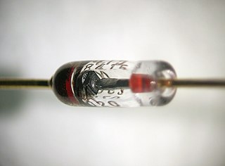
A diode is a two-terminal electronic component that conducts current primarily in one direction. It has low resistance in one direction and high resistance in the other.

<span class="mw-page-title-main">Direct current</span> Unidirectional flow of electric charge

Direct current (DC) is one-directional flow of electric charge. An electrochemical cell is a prime example of DC power. Direct current may flow through a conductor such as a wire, but can also flow through semiconductors, insulators, or even through a vacuum as in electron or ion beams. The electric current flows in a constant direction, distinguishing it from alternating current (AC). A term formerly used for this type of current was galvanic current.

<span class="mw-page-title-main">Rectifier</span> Electrical device that converts AC to DC

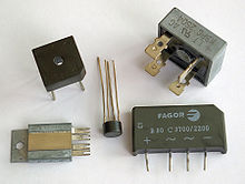
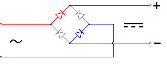
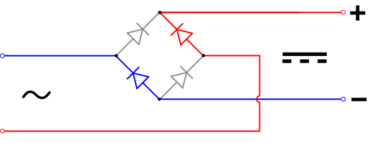
A rectifier is an electrical device that converts alternating current (AC), which periodically reverses direction, to direct current (DC), which flows in only one direction. The reverse operation is performed by an inverter.

<span class="mw-page-title-main">Power inverter</span> Device that changes direct current (DC) to alternating current (AC)

A power inverter, inverter, or invertor is a power electronic device or circuitry that changes direct current (DC) to alternating current (AC). The resulting AC frequency obtained depends on the particular device employed. Inverters do the opposite of rectifiers which were originally large electromechanical devices converting AC to DC.

<span class="mw-page-title-main">Switched-mode power supply</span> Power supply with switching regulator

A switched-mode power supply (SMPS), also called switching-mode power supply, switch-mode power supply, switched power supply, or simply switcher, is an electronic power supply that incorporates a switching regulator to convert electrical power efficiently.

<span class="mw-page-title-main">Envelope detector</span> Electronic circuit

An envelope detector is an electronic circuit that takes a (relatively) high-frequency amplitude modulated signal as input and provides an output, which is the demodulated envelope of the original signal.

A DC-to-DC converter is an electronic circuit or electromechanical device that converts a source of direct current (DC) from one voltage level to another. It is a type of electric power converter. Power levels range from very low to very high.

<span class="mw-page-title-main">Voltage regulator</span> System designed to maintain a constant voltage

A voltage regulator is a system designed to automatically maintain a constant voltage. It may use a simple feed-forward design or may include negative feedback. It may use an electromechanical mechanism, or electronic components. Depending on the design, it may be used to regulate one or more AC or DC voltages.

<span class="mw-page-title-main">Voltage multiplier</span> Electrical circuit power converter

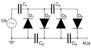
A voltage multiplier is an electrical circuit that converts AC electrical power from a lower voltage to a higher DC voltage, typically using a network of capacitors and diodes.

<span class="mw-page-title-main">Power electronics</span> Technology of power electronics

Power electronics is the application of electronics to the control and conversion of electric power.

<span class="mw-page-title-main">Mercury-arc valve</span> Type of electrical rectifier with a liquid cathode

A mercury-arc valve or mercury-vapor rectifier or (UK) mercury-arc rectifier is a type of electrical rectifier used for converting high-voltage or high-current alternating current (AC) into direct current (DC). It is a type of cold cathode gas-filled tube, but is unusual in that the cathode, instead of being solid, is made from a pool of liquid mercury and is therefore self-restoring. As a result mercury-arc valves, when used as intended, are far more robust and durable and can carry much higher currents than most other types of gas discharge tube. Some examples have been in continuous service, rectifying 50-ampere currents, for decades.

A voltage doubler is an electronic circuit which charges capacitors from the input voltage and switches these charges in such a way that, in the ideal case, exactly twice the voltage is produced at the output as at its input.

<span class="mw-page-title-main">Leo Graetz</span> German physicist

Leo Graetz was a German physicist. He was born in Breslau, Germany, and was the son of historian Heinrich Graetz.

<span class="mw-page-title-main">Cockcroft–Walton generator</span> Electric circuit that generates high DC voltage from low-voltage AC or pulsing DC input

The Cockcroft–Walton (CW) generator, or multiplier, is an electric circuit that generates a high DC voltage from a low-voltage AC or pulsing DC input. It was named after the British and Irish physicists John Douglas Cockcroft and Ernest Thomas Sinton Walton, who in 1932 used this circuit design to power their particle accelerator, performing the first artificial nuclear disintegration in history. They used this voltage multiplier cascade for most of their research, which in 1951 won them the Nobel Prize in Physics for "Transmutation of atomic nuclei by artificially accelerated atomic particles".

The precision rectifier is a configuration obtained with an operational amplifier in order to have a circuit behave like an ideal diode and rectifier.

An H-bridge is an electronic circuit that switches the polarity of a voltage applied to a load. These circuits are often used in robotics and other applications to allow DC motors to run forwards or backwards. The name is derived from its common schematic diagram representation, with four switching elements configured as the branches of a letter "H" and the load connected as the cross-bar.

Ripple in electronics is the residual periodic variation of the DC voltage within a power supply which has been derived from an alternating current (AC) source. This ripple is due to incomplete suppression of the alternating waveform after rectification. Ripple voltage originates as the output of a rectifier or from generation and commutation of DC power.

<span class="mw-page-title-main">Active rectification</span>

Active rectification, or synchronous rectification, is a technique for improving the efficiency of rectification by replacing diodes with actively controlled switches, usually power MOSFETs or power bipolar junction transistors (BJT). Whereas normal semiconductor diodes have a roughly fixed voltage drop of around 0.5 to 1 volts, active rectifiers behave as resistances, and can have arbitrarily low voltage drop.

An HVDC converter converts electric power from high voltage alternating current (AC) to high-voltage direct current (HVDC), or vice versa. HVDC is used as an alternative to AC for transmitting electrical energy over long distances or between AC power systems of different frequencies. HVDC converters capable of converting up to two gigawatts (GW) and with voltage ratings of up to 900 kilovolts (kV) have been built, and even higher ratings are technically feasible. A complete converter station may contain several such converters in series and/or parallel to achieve total system DC voltage ratings of up to 1,100 kV.

This glossary of power electronics is a list of definitions of terms and concepts related to power electronics in general and power electronic capacitors in particular. For more definitions in electric engineering, see Glossary of electrical and electronics engineering. For terms related to engineering in general, see Glossary of engineering.

References

  1. Yazdani, Amirnaser; Iravani, Reza. Voltage-Sourced Converters in Power Systems Modeling, Control, and Applications. Willey. ISBN   9780470521564.
  2. Horowitz, Paul; Hill, Winfield (1989). The Art of Electronics (Second ed.). Cambridge University Press. pp.  44–47. ISBN   0-521-37095-7.
  3. British patent 24398.
  4. (Graetz, 1897), p. 327 footnote.
  5. (Editorial staff) (24 June 1897). "Ein neues Gleichrichter-Verfahren" [A new method of rectification]. Elektrotechnische Zeitschrift (in German). 18 (25): 359 and footnote.
  6. See:
  7. Strzelecki, Ryszard Michal; Benysek, Grzegorz, eds. (August 29, 2008). Power Electronics in Smart Electrical Energy Networks. Springer. p. 57. ISBN   9781848003187.
  8. "Graetz Flow Control Circuit". Archived from the original on 2013-11-04.
  9. Stutz, Michael (stutz@dsl.org), "Conventional versus electron flow", All About Circuits, Vol. 1, Chapter 1, 2000.
  10. Sears, Francis W.; Zemansky, Mark W.; Young, Hugh D., eds. (1982). University Physics (6th ed.). Addison-Wesely Publishing Co., Inc. p. 685. ISBN   0201071959.
  11. "Bridge Rectifier Circuit - Electronics Basics". The Geek Pub. Retrieved 3 September 2019.
  12. "Reverse Polarity Protection". The Renewable Energy UK Website. Bridge Rectifier for Reverse Polarity Protection. Archived from the original on 4 May 2023. Retrieved 18 December 2023.
  13. "Rectifier", Concise Encyclopedia of Science and Technology, Third Edition, Sybil P. Parker, ed. McGraw-Hill, Inc., 1994, p. 1589.