
Texture mapping is a method for mapping a texture on a computer-generated graphic. "Texture" in this context can be high frequency detail, surface texture, or color.

In 3D computer graphics, normal mapping, or Dot3 bump mapping, is a texture mapping technique used for faking the lighting of bumps and dents – an implementation of bump mapping. It is used to add details without using more polygons. A common use of this technique is to greatly enhance the appearance and details of a low polygon model by generating a normal map from a high polygon model or height map.

In 3D computer graphics, hidden-surface determination is the process of identifying what surfaces and parts of surfaces can be seen from a particular viewing angle. A hidden-surface determination algorithm is a solution to the visibility problem, which was one of the first major problems in the field of 3D computer graphics. The process of hidden-surface determination is sometimes called hiding, and such an algorithm is sometimes called a hider. When referring to line rendering it is known as hidden-line removal. Hidden-surface determination is necessary to render a scene correctly, so that one may not view features hidden behind the model itself, allowing only the naturally viewable portion of the graphic to be visible.

In 3D computer graphics and solid modeling, a polygon mesh is a collection of vertices, edges and faces that defines the shape of a polyhedral object's surface. It simplifies rendering, as in a wire-frame model. The faces usually consist of triangles, quadrilaterals (quads), or other simple convex polygons (n-gons). A polygonal mesh may also be more generally composed of concave polygons, or even polygons with holes.

In computer graphics, a shader is a computer program that calculates the appropriate levels of light, darkness, and color during the rendering of a 3D scene—a process known as shading. Shaders have evolved to perform a variety of specialized functions in computer graphics special effects and video post-processing, as well as general-purpose computing on graphics processing units.

A lightmap is a data structure used in lightmapping, a form of surface caching in which the brightness of surfaces in a virtual scene is pre-calculated and stored in texture maps for later use. Lightmaps are most commonly applied to static objects in applications that use real-time 3D computer graphics, such as video games, in order to provide lighting effects such as global illumination at a relatively low computational cost.

Parallax mapping is an enhancement of the bump mapping or normal mapping techniques applied to textures in 3D rendering applications such as video games. To the end user, this means that textures such as stone walls will have more apparent depth and thus greater realism with less of an influence on the performance of the simulation. Parallax mapping was introduced by Tomomichi Kaneko et al., in 2001.

Reyes rendering is a computer software architecture used in 3D computer graphics to render photo-realistic images. It was developed in the mid-1980s by Loren Carpenter and Robert L. Cook at Lucasfilm's Computer Graphics Research Group, which is now Pixar. It was first used in 1982 to render images for the Genesis effect sequence in the movie Star Trek II: The Wrath of Khan. Pixar's RenderMan was an implementation of the Reyes algorithm, It has been deprecated as of 2016 and removed as of RenderMan 21. According to the original paper describing the algorithm, the Reyes image rendering system is "An architecture for fast high-quality rendering of complex images." Reyes was proposed as a collection of algorithms and data processing systems. However, the terms "algorithm" and "architecture" have come to be used synonymously in this context and are used interchangeably in this article.
ATI TruForm was a brand by ATI for a SIP block capable of doing a graphics procedure called tessellation in computer hardware. ATI TruForm was included into Radeon 8500 and newer products.
OBJ is a geometry definition file format first developed by Wavefront Technologies for its Advanced Visualizer animation package. The file format is open and has been adopted by other 3D graphics application vendors.
In computer graphics, reflection mapping or environment mapping is an efficient image-based lighting technique for approximating the appearance of a reflective surface by means of a precomputed texture. The texture is used to store the image of the distant environment surrounding the rendered object.
In 3D computer graphics, a micropolygon is a polygon that is very small relative to the image being rendered. Commonly, the size of a micropolygon is close to or even less than the area of a pixel. Micropolygons allow a renderer to create a highly detailed image.
In computer graphics, per-pixel lighting refers to any technique for lighting an image or scene that calculates illumination for each pixel on a rendered image. This is in contrast to other popular methods of lighting such as vertex lighting, which calculates illumination at each vertex of a 3D model and then interpolates the resulting values over the model's faces to calculate the final per-pixel color values.
In computer graphics, relief mapping is a texture mapping technique first introduced in 2000 used to render the surface details of three-dimensional objects accurately and efficiently. It can produce accurate depictions of self-occlusion, self-shadowing, and parallax. It is a form of short-distance ray tracing done in a pixel shader. Relief mapping is highly comparable in both function and approach to another displacement texture mapping technique, Parallax occlusion mapping, considering that they both rely on ray tracing, though the two are not to be confused with each other, as parallax occlusion mapping uses reverse heightmap tracing.
In computer graphics, a texture mapping unit (TMU) is a component in modern graphics processing units (GPUs). They are able to rotate, resize, and distort a bitmap image to be placed onto an arbitrary plane of a given 3D model as a texture, in a process called texture mapping. In modern graphics cards it is implemented as a discrete stage in a graphics pipeline, whereas when first introduced it was implemented as a separate processor, e.g. as seen on the Voodoo2 graphics card.
Computer graphics lighting is the collection of techniques used to simulate light in computer graphics scenes. While lighting techniques offer flexibility in the level of detail and functionality available, they also operate at different levels of computational demand and complexity. Graphics artists can choose from a variety of light sources, models, shading techniques, and effects to suit the needs of each application.
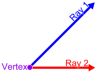
In geometry, a vertex is a point where two or more curves, lines, or edges meet or intersect. As a consequence of this definition, the point where two lines meet to form an angle and the corners of polygons and polyhedra are vertices.

A vertex in computer graphics is a data structure that describes certain attributes, like the position of a point in 2D or 3D space, or multiple points on a surface.

In computer graphics, tessellation is the dividing of datasets of polygons presenting objects in a scene into suitable structures for rendering. Especially for real-time rendering, data is tessellated into triangles, for example in OpenGL 4.0 and Direct3D 11.
This is a glossary of terms relating to computer graphics.

