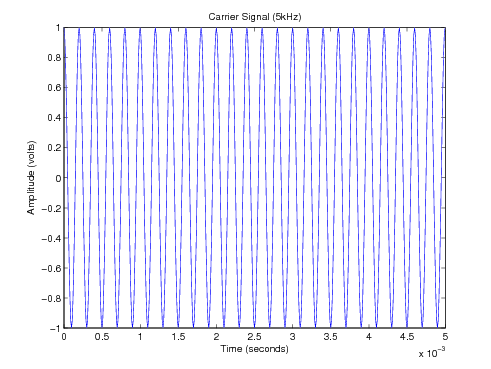
Amplitude modulation (AM) is a modulation technique used in electronic communication, most commonly for transmitting messages with a radio wave. In amplitude modulation, the amplitude of the wave is varied in proportion to that of the message signal, such as an audio signal. This technique contrasts with angle modulation, in which either the frequency of the carrier wave is varied, as in frequency modulation, or its phase, as in phase modulation.
Frequency modulation (FM) is the encoding of information in a carrier wave by varying the instantaneous frequency of the wave. The technology is used in telecommunications, radio broadcasting, signal processing, and computing.
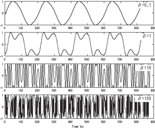
Frequency modulation synthesis is a form of sound synthesis whereby the frequency of a waveform is changed by modulating its frequency with a modulator. The (instantaneous) frequency of an oscillator is altered in accordance with the amplitude of a modulating signal.
Phase modulation (PM) is a modulation pattern for conditioning communication signals for transmission. It encodes a message signal as variations in the instantaneous phase of a carrier wave. Phase modulation is one of the two principal forms of angle modulation, together with frequency modulation.
Quadrature amplitude modulation (QAM) is the name of a family of digital modulation methods and a related family of analog modulation methods widely used in modern telecommunications to transmit information. It conveys two analog message signals, or two digital bit streams, by changing (modulating) the amplitudes of two carrier waves, using the amplitude-shift keying (ASK) digital modulation scheme or amplitude modulation (AM) analog modulation scheme. The two carrier waves are of the same frequency and are out of phase with each other by 90°, a condition known as orthogonality or quadrature. The transmitted signal is created by adding the two carrier waves together. At the receiver, the two waves can be coherently separated (demodulated) because of their orthogonality. Another key property is that the modulations are low-frequency/low-bandwidth waveforms compared to the carrier frequency, which is known as the narrowband assumption.
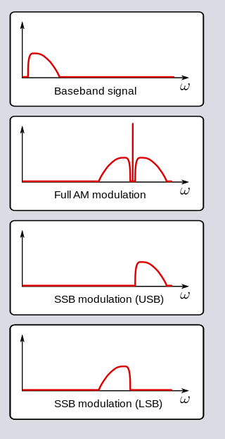
In radio communications, single-sideband modulation (SSB) or single-sideband suppressed-carrier modulation (SSB-SC) is a type of modulation used to transmit information, such as an audio signal, by radio waves. A refinement of amplitude modulation, it uses transmitter power and bandwidth more efficiently. Amplitude modulation produces an output signal the bandwidth of which is twice the maximum frequency of the original baseband signal. Single-sideband modulation avoids this bandwidth increase, and the power wasted on a carrier, at the cost of increased device complexity and more difficult tuning at the receiver.
A Costas loop is a phase-locked loop (PLL) based circuit which is used for carrier frequency recovery from suppressed-carrier modulation signals and phase modulation signals. It was invented by John P. Costas at General Electric in the 1950s. Its invention was described as having had "a profound effect on modern digital communications". The primary application of Costas loops is in wireless receivers. Its advantage over other PLL-based detectors is that at small deviations the Costas loop error voltage is as compared to . This translates to double the sensitivity and also makes the Costas loop uniquely suited for tracking Doppler-shifted carriers, especially in OFDM and GPS receivers.

A phase-locked loop or phase lock loop (PLL) is a control system that generates an output signal whose phase is related to the phase of an input signal. There are several different types; the simplest is an electronic circuit consisting of a variable frequency oscillator and a phase detector in a feedback loop. The oscillator's frequency and phase are controlled proportionally by an applied voltage, hence the term voltage-controlled oscillator (VCO). The oscillator generates a periodic signal of a specific frequency, and the phase detector compares the phase of that signal with the phase of the input periodic signal, to adjust the oscillator to keep the phases matched.
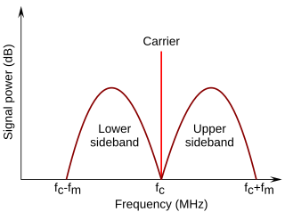
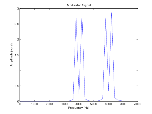
In radio communications, a sideband is a band of frequencies higher than or lower than the carrier frequency, that are the result of the modulation process. The sidebands carry the information transmitted by the radio signal. The sidebands comprise all the spectral components of the modulated signal except the carrier. The signal components above the carrier frequency constitute the upper sideband (USB), and those below the carrier frequency constitute the lower sideband (LSB). All forms of modulation produce sidebands.

In particle physics, bremsstrahlung is electromagnetic radiation produced by the deceleration of a charged particle when deflected by another charged particle, typically an electron by an atomic nucleus. The moving particle loses kinetic energy, which is converted into radiation, thus satisfying the law of conservation of energy. The term is also used to refer to the process of producing the radiation. Bremsstrahlung has a continuous spectrum, which becomes more intense and whose peak intensity shifts toward higher frequencies as the change of the energy of the decelerated particles increases.
A product detector is a type of demodulator used for AM and SSB signals. Rather than converting the envelope of the signal into the decoded waveform like an envelope detector, the product detector takes the product of the modulated signal and a local oscillator, hence the name. A product detector is a frequency mixer.
In mathematics and signal processing, an analytic signal is a complex-valued function that has no negative frequency components. The real and imaginary parts of an analytic signal are real-valued functions related to each other by the Hilbert transform.

In physics and engineering, a phasor is a complex number representing a sinusoidal function whose amplitude, angular frequency, and initial phase are time-invariant. It is related to a more general concept called analytic representation, which decomposes a sinusoid into the product of a complex constant and a factor depending on time and frequency. The complex constant, which depends on amplitude and phase, is known as a phasor, or complex amplitude, and sinor or even complexor.
In the mathematical description of general relativity, the Boyer–Lindquist coordinates are a generalization of the coordinates used for the metric of a Schwarzschild black hole that can be used to express the metric of a Kerr black hole.

Instantaneous phase and frequency are important concepts in signal processing that occur in the context of the representation and analysis of time-varying functions. The instantaneous phase (also known as local phase or simply phase) of a complex-valued function s(t), is the real-valued function:

A carrier recovery system is a circuit used to estimate and compensate for frequency and phase differences between a received signal's carrier wave and the receiver's local oscillator for the purpose of coherent demodulation.
The Pound–Drever–Hall (PDH) technique is a widely used and powerful approach for stabilizing the frequency of light emitted by a laser by means of locking to a stable cavity. The PDH technique has a broad range of applications including interferometric gravitational wave detectors, atomic physics, and time measurement standards, many of which also use related techniques such as frequency modulation spectroscopy. Named after R. V. Pound, Ronald Drever, and John L. Hall, the PDH technique was described in 1983 by Drever, Hall and others working at the University of Glasgow and the U. S. National Bureau of Standards. This optical technique has many similarities to an older frequency-modulation technique developed by Pound for microwave cavities.
Superheterodyne transmitter is a radio or TV transmitter which uses an intermediate frequency signal in addition to radio frequency signal.

Cantilever magnetometry is the use of a cantilever to measure the magnetic moment of magnetic particles. On the end of cantilever is attached a small piece of magnetic material, which interacts with external magnetic fields and exerts torque on the cantilever. These torques cause the cantilever to oscillate faster or slower, depending on the orientation of the particle's moment with respect to the external field, and the magnitude of the moment. The magnitude of the moment and magnetic anisotropy of the material can be deduced by measuring the cantilever's oscillation frequency versus external field.
The spectrum of a chirp pulse describes its characteristics in terms of its frequency components. This frequency-domain representation is an alternative to the more familiar time-domain waveform, and the two versions are mathematically related by the Fourier transform.
The spectrum is of particular interest when pulses are subject to signal processing. For example, when a chirp pulse is compressed by its matched filter, the resulting waveform contains not only a main narrow pulse but, also, a variety of unwanted artifacts many of which are directly attributable to features in the chirp's spectral characteristics.
The simplest way to derive the spectrum of a chirp, now that computers are widely available, is to sample the time-domain waveform at a frequency well above the Nyquist limit and call up an FFT algorithm to obtain the desired result. As this approach was not an option for the early designers, they resorted to analytic analysis, where possible, or to graphical or approximation methods, otherwise. These early methods still remain helpful, however, as they give additional insight into the behavior and properties of chirps.