
In microelectronics, a dual in-line package is an electronic component package with a rectangular housing and two parallel rows of electrical connecting pins. The package may be through-hole mounted to a printed circuit board (PCB) or inserted in a socket. The dual-inline format was invented by Don Forbes, Rex Rice and Bryant Rogers at Fairchild R&D in 1964, when the restricted number of leads available on circular transistor-style packages became a limitation in the use of integrated circuits. Increasingly complex circuits required more signal and power supply leads ; eventually microprocessors and similar complex devices required more leads than could be put on a DIP package, leading to development of higher-density chip carriers. Furthermore, square and rectangular packages made it easier to route printed-circuit traces beneath the packages.

A printed circuit board (PCB), also called printed wiring board (PWB), is a medium used to connect or "wire" components to one another in a circuit. It takes the form of a laminated sandwich structure of conductive and insulating layers: each of the conductive layers is designed with a pattern of traces, planes and other features etched from one or more sheet layers of copper laminated onto or between sheet layers of a non-conductive substrate. Electrical components may be fixed to conductive pads on the outer layers in the shape designed to accept the component's terminals, generally by means of soldering, to both electrically connect and mechanically fasten them to it. Another manufacturing process adds vias, plated-through holes that allow interconnections between layers.

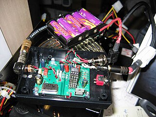
In electronics, point-to-point construction is a non-automated technique for constructing circuits which was widely used before the use of printed circuit boards (PCBs) and automated assembly gradually became widespread following their introduction in the 1950s. Circuits using thermionic valves were relatively large, relatively simple, and used large sockets, all of which made the PCB less obviously advantageous than with later complex semiconductor circuits. Point-to-point construction is still widespread in power electronics, where components are bulky and serviceability is a consideration, and to construct prototype equipment with few or heavy electronic components. A common practice, especially in older point-to-point construction, is to use the leads of components such as resistors and capacitors to bridge as much of the distance between connections as possible, reducing the need to add additional wire between the components.

A breadboard, solderless breadboard, or protoboard is a construction base used to build semi-permanent prototypes of electronic circuits. Unlike a perfboard or stripboard, breadboards do not require soldering or destruction of tracks and are hence reusable. For this reason, breadboards are also popular with students and in technological education.

The Nascom 1 and 2 were single-board computer kits issued in the United Kingdom in 1977 and 1979, respectively, based on the Zilog Z80 and including a keyboard and video interface, a serial port that could be used to store data on a tape cassette using the Kansas City standard, and two 8-bit parallel ports. At that time, including a full keyboard and video display interface was uncommon, as most microcomputer kits were then delivered with only a hexadecimal keypad and seven-segment display. To minimize cost, the buyer had to assemble a Nascom by hand-soldering about 3,000 joints on the single circuit board. Later on, a pre-built, cased machine named Nascom 3 was available; this used the Nascom 2 board.

A ball grid array (BGA) is a type of surface-mount packaging used for integrated circuits. BGA packages are used to permanently mount devices such as microprocessors. A BGA can provide more interconnection pins than can be put on a dual in-line or flat package. The whole bottom surface of the device can be used, instead of just the perimeter. The traces connecting the package's leads to the wires or balls which connect the die to package are also on average shorter than with a perimeter-only type, leading to better performance at high speeds.

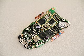
Surface-mount technology (SMT), originally called planar mounting, is a method in which the electrical components are mounted directly onto the surface of a printed circuit board (PCB). An electrical component mounted in this manner is referred to as a surface-mount device (SMD). In industry, this approach has largely replaced the through-hole technology construction method of fitting components, in large part because SMT allows for increased manufacturing automation which reduces cost and improves quality. It also allows for more components to fit on a given area of substrate. Both technologies can be used on the same board, with the through-hole technology often used for components not suitable for surface mounting such as large transformers and heat-sinked power semiconductors.

Stripboard is the generic name for a widely used type of electronics prototyping material for circuit boards characterized by a pre-formed 0.1 inches (2.54 mm) regular (rectangular) grid of holes, with wide parallel strips of copper cladding running in one direction all the way along one side of an insulating bonded paper board. It is commonly also known by the name of the original product Veroboard, which is a trademark, in the UK, of British company Vero Technologies Ltd and Canadian company Pixel Print Ltd. It was originated and developed in the early 1960s by the Electronics Department of Vero Precision Engineering Ltd (VPE). It was introduced as a general-purpose material for use in constructing electronic circuits - differing from purpose-designed printed circuit boards (PCBs) in that a variety of electronics circuits may be constructed using a standard wiring board.

Heathkit is the brand name of kits and other electronic products produced and marketed by the Heath Company. The products over the decades have included electronic test equipment, high fidelity home audio equipment, television receivers, amateur radio equipment, robots, electronic ignition conversion modules for early model cars with point style ignitions, and the influential Heath H-8, H-89, and H-11 hobbyist computers, which were sold in kit form for assembly by the purchaser.

In electronics, through-hole technology is a manufacturing scheme in which leads on the components are inserted through holes drilled in printed circuit boards (PCB) and soldered to pads on the opposite side, either by manual assembly or by the use of automated insertion mount machines.
DIY Audio, do it yourself audio. Rather than buying a piece of possibly expensive audio equipment, such as a high-end audio amplifier or speaker, the person practicing DIY Audio will make it themselves. Alternatively, a DIYer may take an existing manufactured item of vintage era and update or modify it. The benefits of doing so include the satisfaction of creating something enjoyable, the possibility that the equipment made or updated is of higher quality than commercially available products and the pleasure of creating a custom-made device for which no exact equivalent is marketed. Other motivations for DIY audio can include getting audio components at a lower cost, the entertainment of using the item, and being able to ensure quality of workmanship.
In electronics, rework is the repair or refinish of a printed circuit board (PCB) assembly, usually involving desoldering and re-soldering of surface-mounted electronic components (SMD). Mass processing techniques are not applicable to single device repair or replacement, and specialized manual techniques by expert personnel using appropriate equipment are required to replace defective components; area array packages such as ball grid array (BGA) devices particularly require expertise and appropriate tools. A hot air gun or hot air station is used to heat devices and melt solder, and specialised tools are used to pick up and position often tiny components. A rework station is a place to do this work—the tools and supplies for this work, typically on a workbench. Other kinds of rework require other tools.
Founded by David Hafler and Ed Laurent in Philadelphia, Pennsylvania in 1955, Dynaco was an American hi-fi audio system manufacturer popular in the 1960s and 1970s for its wide range of affordable, yet high quality audio components.. Its best known product was the ST-70 tube stereo amplifier. They also manufactured other tube and solid state amplifiers, preamplifiers, radio tuners and bookshelf loudspeakers. Dynaco was liquidated in 1980, and the trademark is now owned by Radial Engineering Ltd.

Perfboard is a material for prototyping electronic circuits. It is a thin, rigid sheet with holes pre-drilled at standard intervals across a grid, usually a square grid of 0.1 inches (2.54 mm) spacing. These holes are ringed by round or square copper pads, though bare boards are also available. Inexpensive perfboard may have pads on only one side of the board, while better quality perfboard can have pads on both sides. Since each pad is electrically isolated, the builder makes all connections with either wire wrap or miniature point to point wiring techniques. Discrete components are soldered to the prototype board such as resistors, capacitors, and integrated circuits. The substrate is typically made of paper laminated with phenolic resin or a fiberglass-reinforced epoxy laminate (FR-4).

Automated optical inspection (AOI) is an automated visual inspection of printed circuit board (PCB) manufacture where a camera autonomously scans the device under test for both catastrophic failure and quality defects. It is commonly used in the manufacturing process because it is a non-contact test method. It is implemented at many stages through the manufacturing process including bare board inspection, solder paste inspection (SPI), pre-reflow and post-re-flow as well as other stages.

In electronics, turret boards were an early attempt at making circuits that were relatively rugged, producible, and serviceable in the days before printed circuit boards (PCBs). As this method was somewhat more expensive than conventional "point-to-point" wiring techniques, it was generally found in the more expensive components, such as professional, commercial, and military audio and test equipment. This is similar to cordwood construction.
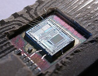
An electronic circuit is composed of individual electronic components, such as resistors, transistors, capacitors, inductors and diodes, connected by conductive wires or traces through which electric current can flow. It is a type of electrical circuit. For a circuit to be referred to as electronic, rather than electrical, generally at least one active component must be present. The combination of components and wires allows various simple and complex operations to be performed: signals can be amplified, computations can be performed, and data can be moved from one place to another.
N8VEM was a homebrew computing project. It featured a variety of free and open hardware and software. N8VEM builders made their own homebrew computer systems for themselves and shared their experiences with other homebrew computer hobbyists. N8VEM homebrew computer components are made in the style of vintage computers of the mid to late 1970s and early 1980s using a mix of classic and modern technologies. They are designed with ease of amateur assembly in mind.

In electronics, prototyping means building an actual circuit to a theoretical design to verify that it works, and to provide a physical platform for debugging it if it does not. The prototype is often constructed using techniques such as wire wrapping or using a breadboard, stripboard or perfboard, with the result being a circuit that is electrically identical to the design but not physically identical to the final product.

