
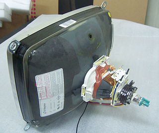
A cathode-ray tube (CRT) is a vacuum tube containing one or more electron guns, which emit electron beams that are manipulated to display images on a phosphorescent screen. The images may represent electrical waveforms on an oscilloscope, a frame of video on an analog television set (TV), digital raster graphics on a computer monitor, or other phenomena like radar targets. A CRT in a TV is commonly called a picture tube. CRTs have also been used as memory devices, in which case the screen is not intended to be visible to an observer. The term cathode ray was used to describe electron beams when they were first discovered, before it was understood that what was emitted from the cathode was a beam of electrons.

An electric current is a flow of charged particles, such as electrons or ions, moving through an electrical conductor or space. It is defined as the net rate of flow of electric charge through a surface. The moving particles are called charge carriers, which may be one of several types of particles, depending on the conductor. In electric circuits the charge carriers are often electrons moving through a wire. In semiconductors they can be electrons or holes. In an electrolyte the charge carriers are ions, while in plasma, an ionized gas, they are ions and electrons.
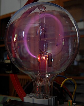
Cathode rays or electron beams (e-beam) are streams of electrons observed in discharge tubes. If an evacuated glass tube is equipped with two electrodes and a voltage is applied, glass behind the positive electrode is observed to glow, due to electrons emitted from the cathode. They were first observed in 1859 by German physicist Julius Plücker and Johann Wilhelm Hittorf, and were named in 1876 by Eugen Goldstein Kathodenstrahlen, or cathode rays. In 1897, British physicist J. J. Thomson showed that cathode rays were composed of a previously unknown negatively charged particle, which was later named the electron. Cathode-ray tubes (CRTs) use a focused beam of electrons deflected by electric or magnetic fields to render an image on a screen.

Sir Joseph John Thomson was a British physicist and Nobel Laureate in Physics, credited with the discovery of the electron, the first subatomic particle to be found.

A linear particle accelerator is a type of particle accelerator that accelerates charged subatomic particles or ions to a high speed by subjecting them to a series of oscillating electric potentials along a linear beamline. The principles for such machines were proposed by Gustav Ising in 1924, while the first machine that worked was constructed by Rolf Widerøe in 1928 at the RWTH Aachen University. Linacs have many applications: they generate X-rays and high energy electrons for medicinal purposes in radiation therapy, serve as particle injectors for higher-energy accelerators, and are used directly to achieve the highest kinetic energy for light particles for particle physics.

The Rutherford scattering experiments were a landmark series of experiments by which scientists learned that every atom has a nucleus where all of its positive charge and most of its mass is concentrated. They deduced this after measuring how an alpha particle beam is scattered when it strikes a thin metal foil. The experiments were performed between 1906 and 1913 by Hans Geiger and Ernest Marsden under the direction of Ernest Rutherford at the Physical Laboratories of the University of Manchester.

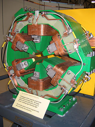
Quadrupole magnets, abbreviated as Q-magnets, consist of groups of four magnets laid out so that in the planar multipole expansion of the field, the dipole terms cancel and where the lowest significant terms in the field equations are quadrupole. Quadrupole magnets are useful as they create a magnetic field whose magnitude grows rapidly with the radial distance from its longitudinal axis. This is used in particle beam focusing.

Electron-beam welding (EBW) is a fusion welding process in which a beam of high-velocity electrons is applied to two materials to be joined. The workpieces melt and flow together as the kinetic energy of the electrons is transformed into heat upon impact. EBW is often performed under vacuum conditions to prevent dissipation of the electron beam.
An electrostatic lens is a device that assists in the transport of charged particles. For instance, it can guide electrons emitted from a sample to an electron analyzer, analogous to the way an optical lens assists in the transport of light in an optical instrument. Systems of electrostatic lenses can be designed in the same way as optical lenses, so electrostatic lenses easily magnify or converge the electron trajectories. An electrostatic lens can also be used to focus an ion beam, for example to make a microbeam for irradiating individual cells.

A Crookes tube is an early experimental electrical discharge tube, with partial vacuum, invented by English physicist William Crookes and others around 1869–1875, in which cathode rays, streams of electrons, were discovered.

A teltron tube (named for Teltron Inc., which is now owned by 3B Scientific Ltd.) is a type of cathode ray tube used to demonstrate the properties of electrons. There were several different types made by Teltron including a diode, a triode, a Maltese Cross tube, a simple deflection tube with a fluorescent screen, and one which could be used to measure the charge-to-mass ratio of an electron. The latter two contained an electron gun with deflecting plates. The beams can be bent by applying voltages to various electrodes in the tube or by holding a magnet close by. The electron beams are visible as fine bluish lines. This is accomplished by filling the tube with low pressure helium (He) or Hydrogen (H2) gas. A few of the electrons in the beam collide with the helium atoms, causing them to fluoresce and emit light.

Electron optics is a mathematical framework for the calculation of electron trajectories in the presence of electromagnetic fields. The term optics is used because magnetic and electrostatic lenses act upon a charged particle beam similarly to optical lenses upon a light beam.
An electron spectrometer is a device used to perform different forms of electron spectroscopy and electron microscopy. This requires analyzing the energy of an incoming beam of electrons. Most electron spectrometers use a hemispherical electron energy analyzer in which the beam of electrons is bent with electric or magnetic fields. Higher energy electrons will be bent less by the beam, this produces a spatially distributed range of energies.
An einzel lens, or unipotential lens, is a charged particle electrostatic lens that focuses without changing the energy of the beam. It consists of three or more sets of cylindrical or rectangular apertures or tubes in series along an axis. It is used in ion optics to focus ions in flight, which is accomplished through manipulation of the electric field in the path of the ions.
A sextupole magnet consist of six magnetic poles set out in an arrangement of alternating north and south poles arranged around an axis. They are used in particle accelerators for the control of chromatic aberrations and for damping the head—tail transverse plasma instability. Two sets of sextupole magnets are used in transmission electron microscopes to correct for spherical aberration.
This is a subdivision of the Oscilloscope article, discussing the various types and models of oscilloscopes in greater detail.
This glossary of physics is a list of definitions of terms and concepts relevant to physics, its sub-disciplines, and related fields, including mechanics, materials science, nuclear physics, particle physics, and thermodynamics. For more inclusive glossaries concerning related fields of science and technology, see Glossary of chemistry terms, Glossary of astronomy, Glossary of areas of mathematics, and Glossary of engineering.

Beam deflection tubes, sometimes known as sheet beam tubes, are vacuum tubes with an electron gun, a beam intensity control grid, a screen grid, sometimes a suppressor grid, and two electrostatic deflection electrodes on opposite sides of the electron beam that can direct the rectangular beam to either of two anodes in the same plane.
A time base generator is a special type of function generator, an electronic circuit that generates a varying voltage to produce a particular waveform. Time base generators produce very high frequency sawtooth waves specifically designed to deflect the beam of a cathode ray tube (CRT) smoothly across the face of the tube and then return it to its starting position.
A deflection yoke is a kind of magnetic lens, used in cathode ray tubes to scan the electron beam both vertically and horizontally over the whole screen.
