In digital logic and computing, a counter is a device which stores the number of times a particular event or process has occurred, often in relationship to a clock. The most common type is a sequential digital logic circuit with an input line called the clock and multiple output lines. The values on the output lines represent a number in the binary or BCD number system. Each pulse applied to the clock input increments or decrements the number in the counter.

In computer science and information theory, a Huffman code is a particular type of optimal prefix code that is commonly used for lossless data compression. The process of finding or using such a code is Huffman coding, an algorithm developed by David A. Huffman while he was a Sc.D. student at MIT, and published in the 1952 paper "A Method for the Construction of Minimum-Redundancy Codes".

In electronics, a multiplexer, also known as a data selector, is a device that selects between several analog or digital input signals and forwards the selected input to a single output line. The selection is directed by a separate set of digital inputs known as select lines. A multiplexer of inputs has select lines, which are used to select which input line to send to the output.
In telecommunication, a convolutional code is a type of error-correcting code that generates parity symbols via the sliding application of a boolean polynomial function to a data stream. The sliding application represents the 'convolution' of the encoder over the data, which gives rise to the term 'convolutional coding'. The sliding nature of the convolutional codes facilitates trellis decoding using a time-invariant trellis. Time invariant trellis decoding allows convolutional codes to be maximum-likelihood soft-decision decoded with reasonable complexity.

In digital logic, an inverter or NOT gate is a logic gate which implements logical negation. It outputs a bit opposite of the bit that is put into it. The bits are typically implemented as two differing voltage levels.
In computer programming, Base64 is a group of binary-to-text encoding schemes that transforms binary data into a sequence of printable characters, limited to a set of 64 unique characters. More specifically, the source binary data is taken 6 bits at a time, then this group of 6 bits is mapped to one of 64 unique characters.
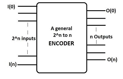
In digital electronics, a binary decoder is a combinational logic circuit that converts binary information from the n coded inputs to a maximum of 2n unique outputs. They are used in a wide variety of applications, including instruction decoding, data multiplexing and data demultiplexing, seven segment displays, and as address decoders for memory and port-mapped I/O.

A barrel shifter is a digital circuit that can shift a data word by a specified number of bits without the use of any sequential logic, only pure combinational logic, i.e. it inherently provides a binary operation. It can however in theory also be used to implement unary operations, such as logical shift left, in cases where limited by a fixed amount. One way to implement a barrel shifter is as a sequence of multiplexers where the output of one multiplexer is connected to the input of the next multiplexer in a way that depends on the shift distance. A barrel shifter is often used to shift and rotate n-bits in modern microprocessors, typically within a single clock cycle.
In computer science, a lookup table (LUT) is an array that replaces runtime computation with a simpler array indexing operation, in a process termed as direct addressing. The savings in processing time can be significant, because retrieving a value from memory is often faster than carrying out an "expensive" computation or input/output operation. The tables may be precalculated and stored in static program storage, calculated as part of a program's initialization phase (memoization), or even stored in hardware in application-specific platforms. Lookup tables are also used extensively to validate input values by matching against a list of valid items in an array and, in some programming languages, may include pointer functions to process the matching input. FPGAs also make extensive use of reconfigurable, hardware-implemented, lookup tables to provide programmable hardware functionality. LUTs differ from hash tables in a way that, to retrieve a value with key , a hash table would store the value in the slot where is a hash function i.e. is used to compute the slot, while in the case of LUT, the value is stored in slot , thus directly addressable.
The Lempel–Ziv–Markov chain algorithm (LZMA) is an algorithm used to perform lossless data compression. It has been under development since either 1996 or 1998 by Igor Pavlov and was first used in the 7z format of the 7-Zip archiver. This algorithm uses a dictionary compression scheme somewhat similar to the LZ77 algorithm published by Abraham Lempel and Jacob Ziv in 1977 and features a high compression ratio and a variable compression-dictionary size, while still maintaining decompression speed similar to other commonly used compression algorithms.
An adder, or summer, is a digital circuit that performs addition of numbers. In many computers and other kinds of processors, adders are used in the arithmetic logic units (ALUs). They are also used in other parts of the processor, where they are used to calculate addresses, table indices, increment and decrement operators and similar operations.
In digital circuits and machine learning, a one-hot is a group of bits among which the legal combinations of values are only those with a single high (1) bit and all the others low (0). A similar implementation in which all bits are '1' except one '0' is sometimes called one-cold. In statistics, dummy variables represent a similar technique for representing categorical data.
A ring counter is a type of counter composed of flip-flops connected into a shift register, with the output of the last flip-flop fed to the input of the first, making a "circular" or "ring" structure.
XOR gate is a digital logic gate that gives a true output when the number of true inputs is odd. An XOR gate implements an exclusive or from mathematical logic; that is, a true output results if one, and only one, of the inputs to the gate is true. If both inputs are false (0/LOW) or both are true, a false output results. XOR represents the inequality function, i.e., the output is true if the inputs are not alike otherwise the output is false. A way to remember XOR is "must have one or the other but not both".
A flash ADC is a type of analog-to-digital converter that uses a linear voltage ladder with a comparator at each "rung" of the ladder to compare the input voltage to successive reference voltages. Often these reference ladders are constructed of many resistors; however, modern implementations show that capacitive voltage division is also possible. The output of these comparators is generally fed into a digital encoder, which converts the inputs into a binary value.
In digital circuits, a logic level is one of a finite number of states that a digital signal can inhabit. Logic levels are usually represented by the voltage difference between the signal and ground, although other standards exist. The range of voltage levels that represent each state depends on the logic family being used. A logic-level shifter can be used to allow compatibility between different circuits.

In computational complexity theory and circuit complexity, a Boolean circuit is a mathematical model for combinational digital logic circuits. A formal language can be decided by a family of Boolean circuits, one circuit for each possible input length.
The Richards controller is a method of implementing a finite-state machine using simple integrated circuits and combinational logic. The method was named after its inventor, Charles L. Richards. It allows for easier design of complex finite-state machines than the traditional techniques of state diagrams, state-transition tables and Boolean algebra offer. Using Richards's technique, it becomes easier to implement finite-state machines with hundreds or even thousands of states.
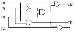
A priority encoder is a circuit or algorithm that compresses multiple binary inputs into a smaller number of outputs, similar to a simple encoder. The output of a priority encoder is the binary representation of the index of the most significant activated line. In contrast to the simple encoder, if two or more inputs to the priority encoder are active at the same time, the input having the highest priority will take precedence. It is an improvement on a simple encoder because it can handle all possible input combinations, but at the cost of extra logic.
State encoding assigns a unique pattern of ones and zeros to each defined state of a finite-state machine (FSM). Traditionally, design criteria for FSM synthesis were speed, area or both. Following Moore's law, with technology advancement, density and speed of integrated circuits have increased exponentially. With this, power dissipation per area has inevitably increased, which has forced designers for portable computing devices and high-speed processors to consider power dissipation as a critical parameter during design consideration.