
Aerodynamics is the study of the motion of air, particularly when affected by a solid object, such as an airplane wing. It involves topics covered in the field of fluid dynamics and its subfield of gas dynamics, and is an important domain of study in aeronautics. The term aerodynamics is often used synonymously with gas dynamics, the difference being that "gas dynamics" applies to the study of the motion of all gases, and is not limited to air. The formal study of aerodynamics began in the modern sense in the eighteenth century, although observations of fundamental concepts such as aerodynamic drag were recorded much earlier. Most of the early efforts in aerodynamics were directed toward achieving heavier-than-air flight, which was first demonstrated by Otto Lilienthal in 1891. Since then, the use of aerodynamics through mathematical analysis, empirical approximations, wind tunnel experimentation, and computer simulations has formed a rational basis for the development of heavier-than-air flight and a number of other technologies. Recent work in aerodynamics has focused on issues related to compressible flow, turbulence, and boundary layers and has become increasingly computational in nature.
The Mach number, often only Mach, is a dimensionless quantity in fluid dynamics representing the ratio of flow velocity past a boundary to the local speed of sound. It is named after the Austrian physicist and philosopher Ernst Mach.

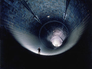
A wind tunnel is "an apparatus for producing a controlled stream of air for conducting aerodynamic experiments". The experiment is conducted in the test section of the wind tunnel and a complete tunnel configuration includes air ducting to and from the test section and a device for keeping the air in motion, such as a fan. Wind tunnel uses include assessing the effects of air on an aircraft in flight or a ground vehicle moving on land, and measuring the effect of wind on buildings and bridges. Wind tunnel test sections range in size from less than a foot across, to over 100 feet (30 m), and with air speeds from a light breeze to hypersonic.

In aerodynamics, a hypersonic speed is one that exceeds five times the speed of sound, often stated as starting at speeds of Mach 5 and above.
Compressible flow is the branch of fluid mechanics that deals with flows having significant changes in fluid density. While all flows are compressible, flows are usually treated as being incompressible when the Mach number is smaller than 0.3. The study of compressible flow is relevant to high-speed aircraft, jet engines, rocket motors, high-speed entry into a planetary atmosphere, gas pipelines, commercial applications such as abrasive blasting, and many other fields.
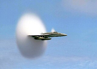
Transonic flow is air flowing around an object at a speed that generates regions of both subsonic and supersonic airflow around that object. The exact range of speeds depends on the object's critical Mach number, but transonic flow is seen at flight speeds close to the speed of sound, typically between Mach 0.8 and 1.2.
A refrigerator designed to reach cryogenic temperatures is often called a cryocooler. The term is most often used for smaller systems, typically table-top size, with input powers less than about 20 kW. Some can have input powers as low as 2–3 W. Large systems, such as those used for cooling the superconducting magnets in particle accelerators are more often called cryogenic refrigerators. Their input powers can be as high as 1 MW. In most cases cryocoolers use a cryogenic fluid as the working substance and employ moving parts to cycle the fluid around a thermodynamic cycle. The fluid is typically compressed at room temperature, precooled in a heat exchanger, then expanded at some low temperature. The returning low-pressure fluid passes through the heat exchanger to precool the high-pressure fluid before entering the compressor intake. The cycle is then repeated.
Transonic wind tunnels, between Mach 0.75 and Mach 1.2, are designed on similar principles as subsonic tunnels but present additional challenges, primarily due to the reflection of shock waves from the walls of the test section. To mitigate this, perforated or slotted walls are used to reduce shock reflection. In transonic testing, both Mach number and Reynolds number are critical and must be properly simulated. This often necessitates the use of large-scale facilities and pressurized or cryogenic wind tunnels. These tunnels are crucial for studying aerodynamic properties of objects at speeds approaching and surpassing the speed of sound, such as high-speed aircraft and spacecraft during critical phases of flight.

A hypersonic wind tunnel is designed to generate a hypersonic flow field in the working section, thus simulating the typical flow features of this flow regime - including compression shocks and pronounced boundary layer effects, entropy layer and viscous interaction zones and most importantly high total temperatures of the flow. The speed of these tunnels vary from Mach 5 to 15. The power requirement of a wind tunnel increases linearly with its cross section and flow density, but cubically with the test velocity required. Hence installation of a continuous, closed circuit wind tunnel remains a costly affair. The first continuous Mach 7-10 wind tunnel with 1x1 m test section was planned at Kochel am See, Germany during WW II and finally put into operation as 'Tunnel A' in the late 1950s at AEDC Tullahoma, TN, USA for an installed power of 57 MW. In view of these high facility demands, also intermittently operated experimental facilities like blow-down wind tunnels are designed and installed to simulate the hypersonic flow. A hypersonic wind tunnel comprises in flow direction the main components: heater/cooler arrangements, dryer, convergent/divergent nozzle, test section, second throat and diffuser. A blow-down wind tunnel has a low vacuum reservoir at the back end, while a continuously operated, closed circuit wind tunnel has a high power compressor installation instead. Since the temperature drops with the expanding flow, the air inside the test section has the chance of becoming liquefied. For that reason, preheating is particularly critical.

A supersonic wind tunnel is a wind tunnel that produces supersonic speeds (1.2<M<5) The Mach number and flow are determined by the nozzle geometry. The Reynolds number is varied by changing the density level. Therefore, a high pressure ratio is required. Apart from that, condensation of moisture or even gas liquefaction can occur if the static temperature becomes cold enough. This means that a supersonic wind tunnel usually needs a drying or a pre-heating facility. A supersonic wind tunnel has a large power demand, so most are designed for intermittent instead of continuous operation.
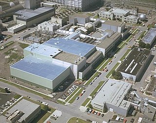
The Unitary Plan Wind Tunnel, located at the NASA Ames Research Center in Moffett Federal Airfield, Mountain View, California, United States, is a research facility used extensively to design and test new generations of aircraft, both commercial and military, as well as NASA space vehicles, including the Space Shuttle. The facility was completed in 1955 and is one of five facilities created after the 1949 Unitary Plan Act supporting aeronautics research.
The University of Texas at Arlington Aerodynamics Research Center (ARC) is a facility located in the southeast portion of the campus operated under the Department of Mechanical and Aerospace Engineering. It was established in 1986 as part of an expansion of UTA's College of Engineering. The ARC contributes to the vision of UTA and the University of Texas System to transform the university into a full-fledged research institution. It showcases the aerodynamics research activities at UTA and, in its history, has established itself as a unique facility at a university level. The wind tunnels and equipment in the facility were mainly built by scouting for and upgrading decommissioned equipment from the government and industry. Currently, Masters and Ph.D. students perform research in the fields of high-speed gas dynamics, propulsion, and Computational fluid dynamics among other projects related to aerodynamics.
Porosity or void fraction is a measure of the void spaces in a material, and is a fraction of the volume of voids over the total volume, between 0 and 1, or as a percentage between 0% and 100%. Strictly speaking, some tests measure the "accessible void", the total amount of void space accessible from the surface.
In aeronautics, expansion and shock tunnels are aerodynamic testing facilities with a specific interest in high speeds and high temperature testing. Shock tunnels use steady flow nozzle expansion whereas expansion tunnels use unsteady expansion with higher enthalpy, or thermal energy. In both cases the gases are compressed and heated until the gases are released, expanding rapidly down the expansion chamber. The tunnels reach speeds from Mach 3 to Mach 30 to create testing conditions that simulate hypersonic to re-entry flight. These tunnels are used by military and government agencies to test hypersonic vehicles that undergo a variety of natural phenomenon that occur during hypersonic flight.
The Aeronautical/Astronautical Research Laboratory (AARL) is an aerospace engineering research facility operated by Ohio State University. It is the principal research facility of the College of Engineering's Department of Aerospace and Astronautical Engineering. It is located on the grounds of Ohio State University Airport, in Columbus, Ohio.

The National Transonic Facility (NTF), also known internally as facility 1236, is a high-pressure, cryogenic, closed-circuit wind tunnel at the Langley Research Center in Hampton, Virginia. It uses nitrogen gas, at high pressure, to cool the air which allows flight aerodynamics to be duplicated in small scale. The cross section of the tunnel is 8.2 feet (2.5 m) high and 8.2 feet (2.5 m) wide. Unlike full-scale wind tunnels, the NTF can adjust airflow to match any model size down to 1/50 scale. The facility can operate at temperatures ranging from -250°F to + 150°F. To achieve lower than ambient temperature, liquid nitrogen is sprayed into the tunnel through nozzles upwind of the fan used to accelerate the air.
The von Karman Gas Dynamics Facility at Arnold Engineering Development Complex, Arnold Air Force Base, Tennessee, provide aerothermal ground test simulations of hypersonic flight over a wide range of velocities and pressure altitudes. The facility consists of three Hypersonic wind tunnels: Tunnel A, B, and C. The wind tunnels can be run for several hours at a time thanks to a 92,500 horsepower air compressor plant system. The test unit is owned by the United States Air Force and operated by National Aerospace Solutions.
The Propulsion Wind Tunnel Facility, located at Arnold Engineering Development Complex, Arnold Air Force Base, Tennessee, holds three wind tunnels: the 16-foot transonic (16T), 16-foot supersonic (16S), and the aerodynamic 4-foot transonic (4T) tunnels. The facility is devoted to aerodynamic and propulsion integration testing of large-scale aircraft models. The tunnels are powered by a large compressor plant which allows the wind tunnels to run for extended periods of time. The test unit is owned by the United States Air Force and operated by Aerospace Testing Alliance.
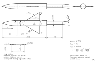
AGARD-B is a standard wind tunnel model that is used to verify, by comparison of test results with previously published data, the measurement chain in a wind tunnel. Together with its derivative AGARD-C it belongs to a family of AGARD standard wind tunnel models. Its origin dates to the year 1952, and the Second Meeting of the AGARD Wind Tunnel and Model Testing Panel in Rome, Italy, when it was decided to define two standard wind tunnel model configurations to be used for exchange of test data and comparison of test results of same models tested in different wind tunnels. The idea was to establish standards of comparison between wind tunnels and improve the validity of wind tunnel tests. Among the standard wind tunnel models, AGARD model configuration B (AGARD-B) has become by far the most popular. Initially intended for the supersonic wind tunnels, the AGARD-B configuration has since been tested in many wind tunnels at a wide range of Mach numbers, from low subsonic, through transonic to hypersonic. Therefore, a considerable database of test results is available.
