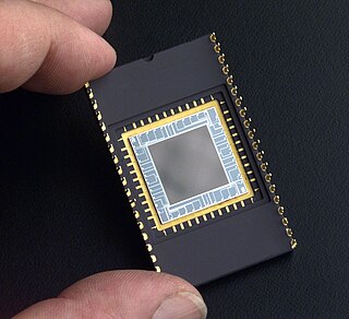
A charge-coupled device (CCD) is an integrated circuit containing an array of linked, or coupled, capacitors. Under the control of an external circuit, each capacitor can transfer its electric charge to a neighboring capacitor. CCD sensors are a major technology used in digital imaging.

In optics, the Airy disk and Airy pattern are descriptions of the best-focused spot of light that a perfect lens with a circular aperture can make, limited by the diffraction of light. The Airy disk is of importance in physics, optics, and astronomy.

Photodetectors, also called photosensors, are sensors of light or other electromagnetic radiation. There are a wide variety of photodetectors which may be classified by mechanism of detection, such as photoelectric or photochemical effects, or by various performance metrics, such as spectral response. Semiconductor-based photodetectors typically use a p–n junction that converts photons into charge. The absorbed photons make electron–hole pairs in the depletion region. Photodiodes and photo transistors are a few examples of photo detectors. Solar cells convert some of the light energy absorbed into electrical energy.
Optical resolution describes the ability of an imaging system to resolve detail, in the object that is being imaged. An imaging system may have many individual components, including one or more lenses, and/or recording and display components. Each of these contributes to the optical resolution of the system; the environment in which the imaging is done often is a further important factor.
Fixed-pattern noise (FPN) is the term given to a particular noise pattern on digital imaging sensors often noticeable during longer exposure shots where particular pixels are susceptible to giving brighter intensities above the average intensity.

Image noise is random variation of brightness or color information in images, and is usually an aspect of electronic noise. It can be produced by the image sensor and circuitry of a scanner or digital camera. Image noise can also originate in film grain and in the unavoidable shot noise of an ideal photon detector. Image noise is an undesirable by-product of image capture that obscures the desired information. Typically the term “image noise” is used to refer to noise in 2D images, not 3D images.
Phase-contrast imaging is a method of imaging that has a range of different applications. It measures differences in the refractive index of different materials to differentiate between structures under analysis. In conventional light microscopy, phase contrast can be employed to distinguish between structures of similar transparency, and to examine crystals on the basis of their double refraction. This has uses in biological, medical and geological science. In X-ray tomography, the same physical principles can be used to increase image contrast by highlighting small details of differing refractive index within structures that are otherwise uniform. In transmission electron microscopy (TEM), phase contrast enables very high resolution (HR) imaging, making it possible to distinguish features a few Angstrom apart.
A staring array, also known as staring-plane array or focal-plane array (FPA), is an image sensor consisting of an array of light-sensing pixels at the focal plane of a lens. FPAs are used most commonly for imaging purposes, but can also be used for non-imaging purposes such as spectrometry, LIDAR, and wave-front sensing.

The optical transfer function (OTF) of an optical system such as a camera, microscope, human eye, or projector specifies how different spatial frequencies are captured or transmitted. It is used by optical engineers to describe how the optics project light from the object or scene onto a photographic film, detector array, retina, screen, or simply the next item in the optical transmission chain. A variant, the modulation transfer function (MTF), neglects phase effects, but is equivalent to the OTF in many situations.
The following are common definitions related to the machine vision field.

Histogram equalization is a method in image processing of contrast adjustment using the image's histogram.

In digital photography, the image sensor format is the shape and size of the image sensor.
Compressed sensing is a signal processing technique for efficiently acquiring and reconstructing a signal, by finding solutions to underdetermined linear systems. This is based on the principle that, through optimization, the sparsity of a signal can be exploited to recover it from far fewer samples than required by the Nyquist–Shannon sampling theorem. There are two conditions under which recovery is possible. The first one is sparsity, which requires the signal to be sparse in some domain. The second one is incoherence, which is applied through the isometric property, which is sufficient for sparse signals. Compressed sensing has applications in, for example, MRI where the incoherence condition is typically satisfied.
The gaseous detection device (GDD) is a method and apparatus for the detection of signals in the gaseous environment of an environmental scanning electron microscope (ESEM) and all scanned beam type of instruments that allow a minimum gas pressure for the detector to operate.

Flat-panel detectors are a class of solid-state x-ray digital radiography devices similar in principle to the image sensors used in digital photography and video. They are used in both projectional radiography and as an alternative to x-ray image intensifiers (IIs) in fluoroscopy equipment.
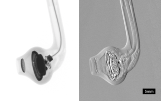
Phase-contrast X-ray imaging or phase-sensitive X-ray imaging is a general term for different technical methods that use information concerning changes in the phase of an X-ray beam that passes through an object in order to create its images. Standard X-ray imaging techniques like radiography or computed tomography (CT) rely on a decrease of the X-ray beam's intensity (attenuation) when traversing the sample, which can be measured directly with the assistance of an X-ray detector. However, in phase contrast X-ray imaging, the beam's phase shift caused by the sample is not measured directly, but is transformed into variations in intensity, which then can be recorded by the detector.

X-ray detectors are devices used to measure the flux, spatial distribution, spectrum, and/or other properties of X-rays.

X-ray computed tomography operates by using an X-ray generator that rotates around the object; X-ray detectors are positioned on the opposite side of the circle from the X-ray source.
Photon-counting computed tomography (PCCT) is a form of X-ray computed tomography (CT) in which X-rays are detected using a photon-counting detector (PCD) which registers the interactions of individual photons. By keeping track of the deposited energy in each interaction, the detector pixels of a PCD each record an approximate energy spectrum, making it a spectral or energy-resolved CT technique. In contrast, more conventional CT scanners use energy-integrating detectors (EIDs), where the total energy deposited in a pixel during a fixed period of time is registered. These EIDs thus register only photon intensity, comparable to black-and-white photography, whereas PCDs register also spectral information, similar to color photography.

There are a variety of technologies available for detecting and recording the images, diffraction patterns, and electron energy loss spectra produced using transmission electron microscopy (TEM).


