
In continuum mechanics, stress is a physical quantity that describes forces present during deformation. For example, an object being pulled apart, such as a stretched elastic band, is subject to tensile stress and may undergo elongation. An object being pushed together, such as a crumpled sponge, is subject to compressive stress and may undergo shortening. The greater the force and the smaller the cross-sectional area of the body on which it acts, the greater the stress. Stress has dimension of force per area, with SI units of newtons per square meter (N/m2) or pascal (Pa).

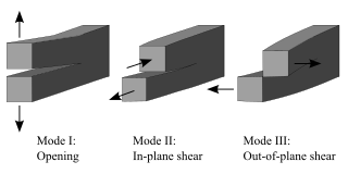
Fracture is the appearance of a crack or complete separation of an object or material into two or more pieces under the action of stress. The fracture of a solid usually occurs due to the development of certain displacement discontinuity surfaces within the solid. If a displacement develops perpendicular to the surface, it is called a normal tensile crack or simply a crack; if a displacement develops tangentially, it is called a shear crack, slip band or dislocation.
The field of strength of materials typically refers to various methods of calculating the stresses and strains in structural members, such as beams, columns, and shafts. The methods employed to predict the response of a structure under loading and its susceptibility to various failure modes takes into account the properties of the materials such as its yield strength, ultimate strength, Young's modulus, and Poisson's ratio. In addition, the mechanical element's macroscopic properties such as its length, width, thickness, boundary constraints and abrupt changes in geometry such as holes are considered.

In materials science, fatigue is the initiation and propagation of cracks in a material due to cyclic loading. Once a fatigue crack has initiated, it grows a small amount with each loading cycle, typically producing striations on some parts of the fracture surface. The crack will continue to grow until it reaches a critical size, which occurs when the stress intensity factor of the crack exceeds the fracture toughness of the material, producing rapid propagation and typically complete fracture of the structure.

In solid mechanics, a stress concentration is a location in an object where the stress is significantly greater than the surrounding region. Stress concentrations occur when there are irregularities in the geometry or material of a structural component that cause an interruption to the flow of stress. This arises from such details as holes, grooves, notches and fillets. Stress concentrations may also occur from accidental damage such as nicks and scratches.
Fracture mechanics is the field of mechanics concerned with the study of the propagation of cracks in materials. It uses methods of analytical solid mechanics to calculate the driving force on a crack and those of experimental solid mechanics to characterize the material's resistance to fracture.

In materials science and solid mechanics, residual stresses are stresses that remain in a solid material after the original cause of the stresses has been removed. Residual stress may be desirable or undesirable. For example, laser peening imparts deep beneficial compressive residual stresses into metal components such as turbine engine fan blades, and it is used in toughened glass to allow for large, thin, crack- and scratch-resistant glass displays on smartphones. However, unintended residual stress in a designed structure may cause it to fail prematurely.
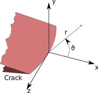
In fracture mechanics, the stress intensity factor is used to predict the stress state near the tip of a crack or notch caused by a remote load or residual stresses. It is a theoretical construct usually applied to a homogeneous, linear elastic material and is useful for providing a failure criterion for brittle materials, and is a critical technique in the discipline of damage tolerance. The concept can also be applied to materials that exhibit small-scale yielding at a crack tip.

Stress corrosion cracking (SCC) is the growth of crack formation in a corrosive environment. It can lead to unexpected and sudden failure of normally ductile metal alloys subjected to a tensile stress, especially at elevated temperature. SCC is highly chemically specific in that certain alloys are likely to undergo SCC only when exposed to a small number of chemical environments. The chemical environment that causes SCC for a given alloy is often one which is only mildly corrosive to the metal. Hence, metal parts with severe SCC can appear bright and shiny, while being filled with microscopic cracks. This factor makes it common for SCC to go undetected prior to failure. SCC often progresses rapidly, and is more common among alloys than pure metals. The specific environment is of crucial importance, and only very small concentrations of certain highly active chemicals are needed to produce catastrophic cracking, often leading to devastating and unexpected failure.
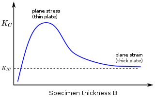
In materials science, fracture toughness is the critical stress intensity factor of a sharp crack where propagation of the crack suddenly becomes rapid and unlimited. A component's thickness affects the constraint conditions at the tip of a crack with thin components having plane stress conditions and thick components having plane strain conditions. Plane strain conditions give the lowest fracture toughness value which is a material property. The critical value of stress intensity factor in mode I loading measured under plane strain conditions is known as the plane strain fracture toughness, denoted . When a test fails to meet the thickness and other test requirements that are in place to ensure plane strain conditions, the fracture toughness value produced is given the designation . Fracture toughness is a quantitative way of expressing a material's resistance to crack propagation and standard values for a given material are generally available.
The J-integral represents a way to calculate the strain energy release rate, or work (energy) per unit fracture surface area, in a material. The theoretical concept of J-integral was developed in 1967 by G. P. Cherepanov and independently in 1968 by James R. Rice, who showed that an energetic contour path integral was independent of the path around a crack.
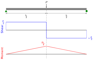
In solid mechanics, a bending moment is the reaction induced in a structural element when an external force or moment is applied to the element, causing the element to bend. The most common or simplest structural element subjected to bending moments is the beam. The diagram shows a beam which is simply supported at both ends; the ends can only react to the shear loads. Other beams can have both ends fixed ; therefore each end support has both bending moments and shear reaction loads. Beams can also have one end fixed and one end simply supported. The simplest type of beam is the cantilever, which is fixed at one end and is free at the other end. In reality, beam supports are usually neither absolutely fixed nor absolutely rotating freely.

A fracture is any separation in a geologic formation, such as a joint or a fault that divides the rock into two or more pieces. A fracture will sometimes form a deep fissure or crevice in the rock. Fractures are commonly caused by stress exceeding the rock strength, causing the rock to lose cohesion along its weakest plane. Fractures can provide permeability for fluid movement, such as water or hydrocarbons. Highly fractured rocks can make good aquifers or hydrocarbon reservoirs, since they may possess both significant permeability and fracture porosity.

Anchor bolts are used to connect structural and non-structural elements to concrete. The connection can be made by a variety of different components: anchor bolts, steel plates, or stiffeners. Anchor bolts transfer different types of load: tension forces and shear forces.

Fractography is the study of the fracture surfaces of materials. Fractographic methods are routinely used to determine the cause of failure in engineering structures, especially in product failure and the practice of forensic engineering or failure analysis. In material science research, fractography is used to develop and evaluate theoretical models of crack growth behavior.
AFGROW is a Damage Tolerance Analysis (DTA) computer program that calculates crack initiation, fatigue crack growth, and fracture to predict the life of metallic structures. Originally developed by the Air Force Research Laboratory, AFGROW is mainly used for aerospace applications, but can be applied to any type of metallic structure that experiences fatigue cracking.
Material failure theory is an interdisciplinary field of materials science and solid mechanics which attempts to predict the conditions under which solid materials fail under the action of external loads. The failure of a material is usually classified into brittle failure (fracture) or ductile failure (yield). Depending on the conditions most materials can fail in a brittle or ductile manner or both. However, for most practical situations, a material may be classified as either brittle or ductile.
The wafer bond characterization is based on different methods and tests. Considered a high importance of the wafer are the successful bonded wafers without flaws. Those flaws can be caused by void formation in the interface due to unevenness or impurities. The bond connection is characterized for wafer bond development or quality assessment of fabricated wafers and sensors.
Polymer fracture is the study of the fracture surface of an already failed material to determine the method of crack formation and extension in polymers both fiber reinforced and otherwise. Failure in polymer components can occur at relatively low stress levels, far below the tensile strength because of four major reasons: long term stress or creep rupture, cyclic stresses or fatigue, the presence of structural flaws and stress-cracking agents. Formations of submicroscopic cracks in polymers under load have been studied by x ray scattering techniques and the main regularities of crack formation under different loading conditions have been analyzed. The low strength of polymers compared to theoretically predicted values are mainly due to the many microscopic imperfections found in the material. These defects namely dislocations, crystalline boundaries, amorphous interlayers and block structure can all lead to the non-uniform distribution of mechanical stress.
Lumped damage mechanics or LDM is a branch of structural mechanics that is concerned with the analysis of frame structures. It is based on continuum damage mechanics and fracture mechanics. It combines the ideas of these theories with the concept of plastic hinge LDM can be defined as the fracture mechanics of complex structural systems. In the models of LDM, cracking or local buckling as well as plasticity are lumped at the inelastic hinges. As in continuum damage mechanics, LDM uses state variables to represent the effects of damage on the remaining stiffness and strength of the frame structure. In reinforced concrete structures, the damage state variable quantifies the crack density in the plastic hinge zone; in unreinforced concrete components and steel beams, it is a dimensionless measure of the crack surface; in tubular steel elements, the damage variable measures the degree of local buckling The LDM evolution laws can be derived from continuum damage mechanics or fracture mechanics. In the latter case, concepts such as the energy release rate or the stress intensity factor of a plastic hinge are introduced. LDM allows for the numerical simulation of the collapse of complex structures with a fraction of the computational cost and human effort of its continuum mechanics counterparts. LDM is also a regularization procedure that eliminates the mesh-dependence phenomenon that is observed in structural analysis with local damage models. In addition, LDM method has been implemented in the finite element analysis of crack propagation of steel beam-to-column connections subjected to ultra-low cycle fatigue.
 Figure 1. Force lines in a plate with a hole.
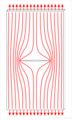 Figure 2. Force lines in a plate with a central crack.
 Figure 3. Force lines in a beam under pure bending.

