Forward converter

Last updated
A schematic showing the most important components of a forward converter. Schematic of a forward converter.png
A schematic showing the most important components of a forward converter.
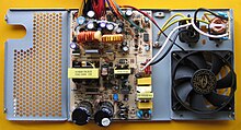
ATX PC Power Supply with Forward Converter (heat sinks are removed for better view) Forward Converter ATX PC Power Supply IMG 1092.jpg
ATX PC Power Supply with Forward Converter (heat sinks are removed for better view)

The forward converter is a DC/DC converter that uses a transformer to increase or decrease the output voltage (depending on the transformer ratio) and provide galvanic isolation for the load. With multiple output windings, it is possible to provide both higher and lower voltage outputs simultaneously.

While it looks superficially like a flyback converter, it operates in a fundamentally different way, and is generally more energy efficient. A flyback converter stores energy in the magnetic field in the transformer air gap during the time the converter switching element (transistor) is conducting. When the switch turns off, the stored magnetic field collapses and the energy is transferred to the output of the flyback converter as electric current. The flyback converter can be viewed as two inductors sharing a common core with opposite polarity windings.

In contrast, the forward converter (which is based on a transformer with same-polarity windings, higher magnetizing inductance, and no air gap) does not store energy during the conduction time of the switching element — transformers cannot store a significant amount of energy, unlike inductors. [1] Instead, energy is passed directly to the output of the forward converter by transformer action during the switch conduction phase.

While the output voltage of a flyback converter is theoretically infinite, the maximum output voltage of the forward converter is constrained by the transformer turns ratio :

where is the pulse width modulator duty cycle.

The forward converter is typically used in off-line supplies to provide an intermediate power output level of 100200 watts. [2]

Related Research Articles

<span class="mw-page-title-main">Inductor</span> Passive two-terminal electrical component that stores energy in its magnetic field

An inductor, also called a coil, choke, or reactor, is a passive two-terminal electrical component that stores energy in a magnetic field when electric current flows through it. An inductor typically consists of an insulated wire wound into a coil.

<span class="mw-page-title-main">Rectifier</span> Electrical device that converts AC to DC

A rectifier is an electrical device that converts alternating current (AC), which periodically reverses direction, to direct current (DC), which flows in only one direction. The reverse operation is performed by an inverter.

<span class="mw-page-title-main">Inductance</span> Property of electrical conductors

Inductance is the tendency of an electrical conductor to oppose a change in the electric current flowing through it. The electric current produces a magnetic field around the conductor. The magnetic field strength depends on the magnitude of the electric current, and follows any changes in the magnitude of the current. From Faraday's law of induction, any change in magnetic field through a circuit induces an electromotive force (EMF) (voltage) in the conductors, a process known as electromagnetic induction. This induced voltage created by the changing current has the effect of opposing the change in current. This is stated by Lenz's law, and the voltage is called back EMF.

<span class="mw-page-title-main">Switched-mode power supply</span> Power supply with switching regulator

A switched-mode power supply (SMPS), also called switching-mode power supply, switch-mode power supply, switched power supply, or simply switcher, is an electronic power supply that incorporates a switching regulator to convert electrical power efficiently.

<span class="mw-page-title-main">Gyrator</span> Two-port non-reciprocal network element

A gyrator is a passive, linear, lossless, two-port electrical network element proposed in 1948 by Bernard D. H. Tellegen as a hypothetical fifth linear element after the resistor, capacitor, inductor and ideal transformer. Unlike the four conventional elements, the gyrator is non-reciprocal. Gyrators permit network realizations of two-(or-more)-port devices which cannot be realized with just the four conventional elements. In particular, gyrators make possible network realizations of isolators and circulators. Gyrators do not however change the range of one-port devices that can be realized. Although the gyrator was conceived as a fifth linear element, its adoption makes both the ideal transformer and either the capacitor or inductor redundant. Thus the number of necessary linear elements is in fact reduced to three. Circuits that function as gyrators can be built with transistors and op-amps using feedback.

<span class="mw-page-title-main">Ćuk converter</span> Type of electrical current converter

The Ćuk converter is a type of buck-boost converter with low ripple current. A Ćuk converter can be seen as a combination of boost converter and buck converter, having one switching device and a mutual capacitor, to couple the energy.

A DC-to-DC converter is an electronic circuit or electromechanical device that converts a source of direct current (DC) from one voltage level to another. It is a type of electric power converter. Power levels range from very low to very high.

<span class="mw-page-title-main">Voltage regulator</span> System designed to maintain a constant voltage

A voltage regulator is a system designed to automatically maintain a constant voltage. It may use a simple feed-forward design or may include negative feedback. It may use an electromechanical mechanism, or electronic components. Depending on the design, it may be used to regulate one or more AC or DC voltages.

<span class="mw-page-title-main">Flyback transformer</span> High frequency pulse transformer, commonly used to drive cathode ray tubes

A flyback transformer (FBT), also called a line output transformer (LOPT), is a special type of electrical transformer. It was initially designed to generate high-voltage sawtooth signals at a relatively high frequency. In modern applications, it is used extensively in switched-mode power supplies for both low (3 V) and high voltage supplies.

<span class="mw-page-title-main">Blocking oscillator</span>

A blocking oscillator is a simple configuration of discrete electronic components which can produce a free-running signal, requiring only a resistor, a transformer, and one amplifying element such as a transistor or vacuum tube. The name is derived from the fact that the amplifying element is cut-off or "blocked" for most of the duty cycle, producing periodic pulses on the principle of a relaxation oscillator. The non-sinusoidal output is not suitable for use as a radio-frequency local oscillator, but it can serve as a timing generator, to power lights, LEDs, EL wire, or small neon indicators. If the output is used as an audio signal, the simple tones are also sufficient for applications such as alarms or a Morse code practice device. Some cameras use a blocking oscillator to strobe the flash prior to a shot to reduce the red-eye effect.

<span class="mw-page-title-main">Boost converter</span> DC-to-DC power converter with an output voltage greater than its input voltage

A boost converter or step-up converter is a DC-to-DC converter that increases voltage, while decreasing current, from its input (supply) to its output (load).

<span class="mw-page-title-main">Buck converter</span> DC-DC voltage step-down power converter

A buck converter or step-down converter is a DC-to-DC converter which decreases voltage, while increasing current, from its input (supply) to its output (load). It is a class of switched-mode power supply. Switching converters provide much greater power efficiency as DC-to-DC converters than linear regulators, which are simpler circuits that dissipate power as heat, but do not step up output current. The efficiency of buck converters can be very high, often over 90%, making them useful for tasks such as converting a computer's main supply voltage, which is usually 12 V, down to lower voltages needed by USB, DRAM and the CPU, which are usually 5, 3.3 or 1.8 V.

<span class="mw-page-title-main">Buck–boost converter</span> Type of DC-to-DC converter

The buck–boost converter is a type of DC-to-DC converter that has an output voltage magnitude that is either greater than or less than the input voltage magnitude. It is equivalent to a flyback converter using a single inductor instead of a transformer. Two different topologies are called buck–boost converter. Both of them can produce a range of output voltages, ranging from much larger than the input voltage, down to almost zero.

An H-bridge is an electronic circuit that switches the polarity of a voltage applied to a load. These circuits are often used in robotics and other applications to allow DC motors to run forwards or backwards. The name is derived from its common schematic diagram representation, with four switching elements configured as the branches of a letter "H" and the load connected as the cross-bar.

<span class="mw-page-title-main">Push–pull converter</span>

A push–pull converter is a type of DC-to-DC converter, a switching converter that uses a transformer to change the voltage of a DC power supply. The distinguishing feature of a push-pull converter is that the transformer primary is supplied with current from the input line by pairs of transistors in a symmetrical push-pull circuit. The transistors are alternately switched on and off, periodically reversing the current in the transformer. Therefore, current is drawn from the line during both halves of the switching cycle. This contrasts with buck-boost converters, in which the input current is supplied by a single transistor which is switched on and off, so current is drawn from the line during only a part of the switching cycle. During the remainder of the cycle, the output power is supplied by energy stored in inductors or capacitors in the power supply. Push–pull converters have steadier input current, create less noise on the input line, and are more efficient in higher power applications.

<span class="mw-page-title-main">Flyback converter</span> Type of voltage converter circuit

The flyback converter is used in both AC/DC, and DC/DC conversion with galvanic isolation between the input and any outputs. The flyback converter is a buck-boost converter with the inductor split to form a transformer, so that the voltage ratios are multiplied with an additional advantage of isolation. When driving, for example, a plasma lamp or a voltage multiplier, the rectifying diode of the boost converter is left out and the device is called a flyback transformer.

<span class="mw-page-title-main">Single-ended primary-inductor converter</span> Electrical device

The single-ended primary-inductor converter (SEPIC) is a type of DC/DC converter that allows the electrical potential (voltage) at its output to be greater than, less than, or equal to that at its input. The output of the SEPIC is controlled by the duty cycle of the control switch (S1).

<span class="mw-page-title-main">Flyback diode</span> Voltage-spike stopping diode across an inductor

A flyback diode is any diode connected across an inductor used to eliminate flyback, which is the sudden voltage spike seen across an inductive load when its supply current is suddenly reduced or interrupted. It is used in circuits in which inductive loads are controlled by switches, and in switching power supplies and inverters.

<span class="mw-page-title-main">Gyrator–capacitor model</span> Model for magnetic circuits

The gyrator–capacitor model - sometimes also the capacitor-permeance model - is a lumped-element model for magnetic circuits, that can be used in place of the more common resistance–reluctance model. The model makes permeance elements analogous to electrical capacitance rather than electrical resistance. Windings are represented as gyrators, interfacing between the electrical circuit and the magnetic model.

This glossary of electrical and electronics engineering is a list of definitions of terms and concepts related specifically to electrical engineering and electronics engineering. For terms related to engineering in general, see Glossary of engineering.

References

  1. Anders Lind, IFNA PMM, (v1.0, March 2013) Design Note AN 2013-03. "Single Transistor Forward Converter Design". Infineon Technologies. Archived from a copy on Digikkey on 2015-09-23.
  2. Hart, Daniel (2010). Power Electronics. William C Brown Publishing. OCLC   436031173.

Rudy Severns (July 2000). "The History of the Forward Converter" (PDF). Switching Power Magazine. Archived from the original (PDF) on July 18, 2014. Retrieved 5 Sep 2012.