Freeform surface modelling

Last updated

Freeform surface modelling is a technique for engineering freeform surfaces with a CAD or CAID system.

Contents

The technology has encompassed two main fields. Either creating aesthetic surfaces (class A surfaces) that also perform a function; for example, car bodies and consumer product outer forms, or technical surfaces for components such as gas turbine blades and other fluid dynamic engineering components.

CAD software packages use two basic methods for the creation of surfaces. The first begins with construction curves (splines) from which the 3D surface is then swept (section along guide rail) or meshed (lofted) through.

A surface being created from curves Ff surface3 t.png
A surface being created from curves

The second method is direct creation of the surface with manipulation of the surface poles/control points.

Surface edit by poles Freeform1.gif
Surface edit by poles

From these initially created surfaces, other surfaces are constructed using either derived methods such as offset or angled extensions from surfaces; or via bridging and blending between groups of surfaces.

Variable smooth blend between surfaces
(animated version) Blend1.png
Variable smooth blend between surfaces
(animated version)

Surfaces

Freeform surface, or freeform surfacing, is used in CAD and other computer graphics software to describe the skin of a 3D geometric element. Freeform surfaces do not have rigid radial dimensions, unlike regular surfaces such as planes, cylinders and conic surfaces. They are used to describe forms such as turbine blades, car bodies and boat hulls. Initially developed for the automotive and aerospace industries, freeform surfacing is now widely used in all engineering design disciplines from consumer goods products to ships. Most systems today use nonuniform rational B-spline (NURBS) mathematics [1] to describe the surface forms; however, there are other methods such as Gordon surfaces or Coons surfaces .

The forms of freeform surfaces (and curves) are not stored or defined in CAD software in terms of polynomial equations, but by their poles, degree, and number of patches (segments with spline curves). The degree of a surface determines its mathematical properties, and can be seen as representing the shape by a polynomial with variables to the power of the degree value. For example, a surface with a degree of 1 would be a flat cross section surface. A surface with degree 2 would be curved in one direction, while a degree 3 surface could (but does not necessarily) change once from concave to convex curvature. Some CAD systems use the term order instead of degree. The order of a polynomial is one greater than the degree, and gives the number of coefficients rather than the greatest exponent.

Example surface pole map Surface modelling.svg
Example surface pole map

The poles (sometimes known as control points ) of a surface define its shape. The natural surface edges are defined by the positions of the first and last poles. (Note that a surface can have trimmed boundaries.) The intermediate poles act like magnets drawing the surface in their direction. The surface does not, however, go through these points. The second and third poles as well as defining shape, respectively determine the start and tangent angles and the curvature. In a single patch surface (Bézier surface), there is one more pole than the degree values of the surface. Surface patches can be merged into a single NURBS surface; at these points are knot lines. The number of knots will determine the influence of the poles on either side and how smooth the transition is. The smoothness between patches, known as continuity, is often referred to in terms of a C value:

Two more important aspects are the U and V parameters. These are values on the surface ranging from 0 to 1, used in the mathematical definition of the surface and for defining paths on the surface: for example, a trimmed boundary edge. Note that they are not proportionally spaced along the surface. A curve of constant U or constant V is known as an isoperimetric curve, or U (V) line. In CAD systems, surfaces are often displayed with their poles of constant U or constant V values connected together by lines; these are known as control polygons.

Modelling

When defining a form, an important factor is the continuity between surfaces - how smoothly they connect to one another.

One example of where surfacing excels is automotive body panels. Just blending two curved areas of the panel with different radii of curvature together, maintaining tangential continuity (meaning that the blended surface doesn't change direction suddenly, but smoothly) won't be enough. They need to have a continuous rate of curvature change between the two sections, or else their reflections will appear disconnected.

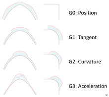
The continuity is defined using the terms:

Curve and line G0, G1, G2 and G3 continuity Geometric continuity.png
Curve and line G0, G1, G2 and G3 continuity

To achieve a high quality NURBS or Bézier surface, degrees of 5 or greater are generally used.

Freeform surface modelling software

See also

Related Research Articles

<span class="mw-page-title-main">Bézier curve</span> Curve used in computer graphics and related fields

A Bézier curve is a parametric curve used in computer graphics and related fields. A set of discrete "control points" defines a smooth, continuous curve by means of a formula. Usually the curve is intended to approximate a real-world shape that otherwise has no mathematical representation or whose representation is unknown or too complicated. The Bézier curve is named after French engineer Pierre Bézier (1910–1999), who used it in the 1960s for designing curves for the bodywork of Renault cars. Other uses include the design of computer fonts and animation. Bézier curves can be combined to form a Bézier spline, or generalized to higher dimensions to form Bézier surfaces. The Bézier triangle is a special case of the latter.

<span class="mw-page-title-main">B-spline</span> Spline function

In the mathematical subfield of numerical analysis, a B-spline or basis spline is a spline function that has minimal support with respect to a given degree, smoothness, and domain partition. Any spline function of given degree can be expressed as a linear combination of B-splines of that degree. Cardinal B-splines have knots that are equidistant from each other. B-splines can be used for curve-fitting and numerical differentiation of experimental data.

<span class="mw-page-title-main">Computer-aided design</span> Constructing a product by means of computer

Computer-aided design (CAD) is the use of computers to aid in the creation, modification, analysis, or optimization of a design. This software is used to increase the productivity of the designer, improve the quality of design, improve communications through documentation, and to create a database for manufacturing. Designs made through CAD software are helpful in protecting products and inventions when used in patent applications. CAD output is often in the form of electronic files for print, machining, or other manufacturing operations. The terms computer-aided drafting (CAD) and computer-aided design and drafting (CADD) are also used.

Bézier surfaces are a species of mathematical spline used in computer graphics, computer-aided design, and finite element modeling. As with Bézier curves, a Bézier surface is defined by a set of control points. Similar to interpolation in many respects, a key difference is that the surface does not, in general, pass through the central control points; rather, it is "stretched" toward them as though each were an attractive force. They are visually intuitive, and for many applications, mathematically convenient.

<span class="mw-page-title-main">Non-uniform rational B-spline</span> Method of representing curves and surfaces in computer graphics

Non-uniform rational basis spline (NURBS) is a mathematical model using basis splines (B-splines) that is commonly used in computer graphics for representing curves and surfaces. It offers great flexibility and precision for handling both analytic and modeled shapes. It is a type of curve modeling, as opposed to polygonal modeling or digital sculpting. NURBS curves are commonly used in computer-aided design (CAD), manufacturing (CAM), and engineering (CAE). They are part of numerous industry-wide standards, such as IGES, STEP, ACIS, and PHIGS. Tools for creating and editing NURBS surfaces are found in various 3D graphics and animation software packages.

Autodesk 3ds Max, formerly 3D Studio and 3D Studio Max, is a professional 3D computer graphics program for making 3D animations, models, games and images. It is developed and produced by Autodesk Media and Entertainment. It has modeling capabilities and a flexible plugin architecture and must be used on the Microsoft Windows platform. It is frequently used by video game developers, many TV commercial studios, and architectural visualization studios. It is also used for movie effects and movie pre-visualization. 3ds Max features shaders, dynamic simulation, particle systems, radiosity, normal map creation and rendering, global illumination, a customizable user interface, and its own scripting language.

<span class="mw-page-title-main">Spline (mathematics)</span> Mathematical function defined piecewise by polynomials

In mathematics, a spline is a special function defined piecewise by polynomials. In interpolating problems, spline interpolation is often preferred to polynomial interpolation because it yields similar results, even when using low degree polynomials, while avoiding Runge's phenomenon for higher degrees.

<span class="mw-page-title-main">Autodesk Alias</span> Industrial design software

Autodesk Alias is a family of computer-aided industrial design (CAID) software predominantly used in automotive design and industrial design for generating class A surfaces using Bézier surface and non-uniform rational B-spline (NURBS) modeling method.

<span class="mw-page-title-main">Curve fitting</span> Process of constructing a curve that has the best fit to a series of data points

Curve fitting is the process of constructing a curve, or mathematical function, that has the best fit to a series of data points, possibly subject to constraints. Curve fitting can involve either interpolation, where an exact fit to the data is required, or smoothing, in which a "smooth" function is constructed that approximately fits the data. A related topic is regression analysis, which focuses more on questions of statistical inference such as how much uncertainty is present in a curve that is fit to data observed with random errors. Fitted curves can be used as an aid for data visualization, to infer values of a function where no data are available, and to summarize the relationships among two or more variables. Extrapolation refers to the use of a fitted curve beyond the range of the observed data, and is subject to a degree of uncertainty since it may reflect the method used to construct the curve as much as it reflects the observed data.

In numerical analysis, a cubic Hermite spline or cubic Hermite interpolator is a spline where each piece is a third-degree polynomial specified in Hermite form, that is, by its values and first derivatives at the end points of the corresponding domain interval.

<span class="mw-page-title-main">Parallel curve</span>

A parallel of a curve is the envelope of a family of congruent circles centered on the curve. It generalises the concept of parallel (straight) lines. It can also be defined as a curve whose points are at a constant normal distance from a given curve. These two definitions are not entirely equivalent as the latter assumes smoothness, whereas the former does not.

<span class="mw-page-title-main">Boundary representation</span> Method of representing a 3D object by defining the limits of its volume

In solid modeling and computer-aided design, boundary representation is a method for representing a 3D shape by defining the limits of its volume. A solid is represented as a collection of connected surface elements, which define the boundary between interior and exterior points.

Paul de Casteljau was a French physicist and mathematician. In 1959, while working at Citroën, he developed an algorithm for evaluating calculations on a certain family of curves, which would later be formalized and popularized by engineer Pierre Bézier, leading to the curves widely known as Bézier curves.

Steven Anson Coons was an early pioneer in the field of computer graphical methods. He was a professor at the Massachusetts Institute of Technology in the Mechanical Engineering Department. He was also a professor at Syracuse University after leaving MIT. Steven Coons had a vision of interactive computer graphics as a design tool to aid the engineer.

<span class="mw-page-title-main">Class A surface</span> Type of surface in automotive design

In automotive design, a class A surface is any of a set of freeform surfaces of high efficiency and quality. Although, strictly, it is nothing more than saying the surfaces have curvature and tangency alignment – to ideal aesthetical reflection quality, many people interpret class A surfaces to have G2 curvature continuity to one another.

Loft is a method to create complicated smooth 3D shapes in CAD and other 3D modeling software. Planar cross-sections of the desired shape are defined at chosen locations. Algorithms find a smooth 3D shape that fit these cross-sections. Designers can modify the shape through choice of fitting algorithm and input parameters. The method is used in packages such as Onshape, 3D Studio Max, Creo*, SolidWorks, NX, Autodesk Revit, and FreeCAD.

<span class="mw-page-title-main">Computer representation of surfaces</span> Method of representing objects in 3D computer graphics

In technical applications of 3D computer graphics (CAx) such as computer-aided design and computer-aided manufacturing, surfaces are one way of representing objects. The other ways are wireframe and solids. Point clouds are also sometimes used as temporary ways to represent an object, with the goal of using the points to create one or more of the three permanent representations.

In computer graphics, a T-spline is a mathematical model for defining freeform surfaces. A T-spline surface is a type of surface defined by a network of control points where a row of control points is allowed to terminate without traversing the entire surface. The control net at a terminated row resembles the letter "T".

Solid Modeling Solutions is a company who has an implementation of a mathematical representation of many NURBS, 3D geometry, and Solid modeling technology which emerged in the 1980s and 1990s into a commercial implementation known as SMLib. This article will provide the background and history of this implementation into a commercial product line from Solid Modeling Solutions (SMS). SMS is an independent supplier of source code for a powerful suite of 3D geometry kernels. SMS provides advanced NURBS-based geometry libraries, SMLib, TSNLib, GSNLib, NLib, SDLib, VSLib, and PolyMLib, that encompass extensive definition and manipulation of NURBS curves and surfaces with the latest fully functional non-manifold topology.

References

  1. Metzger, Michael; Eismann, Sabine. "Freeform Surface Modeling" (PDF). hp.com. Retrieved April 15, 2017.