
Radar is a detection system that uses radio waves to determine the distance (range), angle, or velocity of objects. It can be used to detect aircraft, ships, spacecraft, guided missiles, motor vehicles, weather formations, and terrain. A radar system consists of a transmitter producing electromagnetic waves in the radio or microwaves domain, a transmitting antenna, a receiving antenna and a receiver and processor to determine properties of the object(s). Radio waves from the transmitter reflect off the object and return to the receiver, giving information about the object's location and speed.
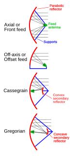
In telecommunications and radar, a Cassegrain antenna is a parabolic antenna in which the feed antenna is mounted at or behind the surface of the concave main parabolic reflector dish and is aimed at a smaller convex secondary reflector suspended in front of the primary reflector. The beam of radio waves from the feed illuminates the secondary reflector, which reflects it back to the main reflector dish, which reflects it forward again to form the desired beam. The Cassegrain design is widely used in parabolic antennas, particularly in large antennas such as those in satellite ground stations, radio telescopes, and communication satellites.

In the field of antenna design the term radiation pattern refers to the directional (angular) dependence of the strength of the radio waves from the antenna or other source.

In telecommunications and radar, a reflective array antenna is a class of directive antennas in which multiple driven elements are mounted in front of a flat surface designed to reflect the radio waves in a desired direction. They are a type of array antenna. They are often used in the VHF and UHF frequency bands. VHF examples are generally large and resemble a highway billboard, so they are sometimes called billboard antennas. Other names are bedspring array and bowtie array depending on the type of elements making up the antenna. The curtain array is a larger version used by shortwave radio broadcasting stations.
In electromagnetics, an antenna's power gain or simply gain is a key performance number which combines the antenna's directivity and electrical efficiency. In a transmitting antenna, the gain describes how well the antenna converts input power into radio waves headed in a specified direction. In a receiving antenna, the gain describes how well the antenna converts radio waves arriving from a specified direction into electrical power. When no direction is specified, gain is understood to refer to the peak value of the gain, the gain in the direction of the antenna's main lobe. A plot of the gain as a function of direction is called the gain pattern or radiation pattern.
A feed horn is a small horn antenna used to couple a waveguide to e.g. a parabolic dish antenna or offset dish antenna for reception or transmission of microwave. A typical application is the use for satellite television reception with a satellite dish. In that case the feed horn can either be a separate part used together with e.g. a "low-noise block downconverter" (LNB), or more typically today is integrated into a "low-noise block feedhorn" (LNBF).

In radio engineering, an antenna or aerial is the interface between radio waves propagating through space and electric currents moving in metal conductors, used with a transmitter or receiver. In transmission, a radio transmitter supplies an electric current to the antenna's terminals, and the antenna radiates the energy from the current as electromagnetic waves. In reception, an antenna intercepts some of the power of a radio wave in order to produce an electric current at its terminals, that is applied to a receiver to be amplified. Antennas are essential components of all radio equipment.

A parabolic antenna is an antenna that uses a parabolic reflector, a curved surface with the cross-sectional shape of a parabola, to direct the radio waves. The most common form is shaped like a dish and is popularly called a dish antenna or parabolic dish. The main advantage of a parabolic antenna is that it has high directivity. It functions similarly to a searchlight or flashlight reflector to direct the radio waves in a narrow beam, or receive radio waves from one particular direction only. Parabolic antennas have some of the highest gains, meaning that they can produce the narrowest beamwidths, of any antenna type. In order to achieve narrow beamwidths, the parabolic reflector must be much larger than the wavelength of the radio waves used, so parabolic antennas are used in the high frequency part of the radio spectrum, at UHF and microwave (SHF) frequencies, at which the wavelengths are small enough that conveniently-sized reflectors can be used.

Effective radiated power (ERP), synonymous with equivalent radiated power, is an IEEE standardized definition of directional radio frequency (RF) power, such as that emitted by a radio transmitter. It is the total power in watts that would have to be radiated by a half-wave dipole antenna to give the same radiation intensity as the actual source antenna at a distant receiver located in the direction of the antenna's strongest beam. ERP measures the combination of the power emitted by the transmitter and the ability of the antenna to direct that power in a given direction. It is equal to the input power to the antenna multiplied by the gain of the antenna. It is used in electronics and telecommunications, particularly in broadcasting to quantify the apparent power of a broadcasting station experienced by listeners in its reception area.

A Yagi–Uda antenna or simply Yagi antenna, is a directional antenna consisting of two or more parallel resonant antenna elements in an end-fire array; these elements are most often metal rods acting as half-wave dipoles. Yagi–Uda antennas consist of a single driven element connected to a radio transmitter and/or receiver through a transmission line, and additional "parasitic elements" with no electrical connection, usually including one so-called reflector and any number of directors. It was invented in 1926 by Shintaro Uda of Tohoku Imperial University, Japan, with a lesser role played by his colleague Hidetsugu Yagi.

A directional antenna or beam antenna is an antenna which radiates or receives greater power in specific directions allowing increased performance and reduced interference from unwanted sources. Directional antennas provide increased performance over dipole antennas—or omnidirectional antennas in general—when greater concentration of radiation in a certain direction is desired.

Direction finding (DF), or radio direction finding (RDF), is the measurement of the direction from which a received signal was transmitted. This can refer to radio or other forms of wireless communication, including radar signals detection and monitoring (ELINT/ESM). By combining the direction information from two or more suitably spaced receivers, the source of a transmission may be located via triangulation. Radio direction finding is used in the navigation of ships and aircraft, to locate emergency transmitters for search and rescue, for tracking wildlife, and to locate illegal or interfering transmitters. RDF was important in combating German threats during both the World War II Battle of Britain and the long running Battle of the Atlantic. In the former, the Air Ministry also used RDF to locate its own fighter groups and vector them to detected German raids.

A horn antenna or microwave horn is an antenna that consists of a flaring metal waveguide shaped like a horn to direct radio waves in a beam. Horns are widely used as antennas at UHF and microwave frequencies, above 300 MHz. They are used as feed antennas for larger antenna structures such as parabolic antennas, as standard calibration antennas to measure the gain of other antennas, and as directive antennas for such devices as radar guns, automatic door openers, and microwave radiometers. Their advantages are moderate directivity, low standing wave ratio (SWR), broad bandwidth, and simple construction and adjustment.

An orthomode transducer (OMT) is a waveguide component. It is commonly referred to as a polarisation duplexer. Orthomode transducers serve either to combine or to separate two orthogonally polarized microwave signal paths. One of the paths forms the uplink, which is transmitted over the same waveguide as the received signal path, or downlink path. Such a device may be part of a VSAT antenna feed or a terrestrial microwave radio feed; for example, OMTs are often used with a feed horn to isolate orthogonal polarizations of a signal and to transfer transmit and receive signals to different ports.

An antenna reflector is a device that reflects electromagnetic waves. Antenna reflectors can exist as a standalone device for redirecting radio frequency (RF) energy, or can be integrated as part of an antenna assembly.

Conical scanning is a system used in early radar units to improve their accuracy, as well as making it easier to steer the antenna properly to point at a target. Conical scanning is similar in concept to the earlier lobe switching concept used on some of the earliest radars, and many examples of lobe switching sets were modified in the field to conical scanning during World War II, notably the German Würzburg radar. Antenna guidance can be made entirely automatic, as in the American SCR-584. Potential failure modes and susceptibility to deception jamming led to the replacement of conical scan systems with monopulse radar sets. They are still used by the Deep Space Network for maintaining communications links to space probes. The spin-stabilized Pioneer 10 and Pioneer 11 probes used onboard conical scanning maneuvers to track Earth in its orbit.
Monopulse radar is a radar system that uses additional encoding of the radio signal to provide accurate directional information. The name refers to its ability to extract range and direction from a single signal pulse.

In microwave systems, a spiral antenna is a type of RF antenna. It is shaped as a two-arm spiral, or more arms may be used. Spiral antennas were first described in 1956. Spiral antennas belong to the class of frequency independent antennas which operate over a wide range of frequencies. Polarization, radiation pattern and impedance of such antennas remain unchanged over large bandwidth. Such antennas are inherently circularly polarized with low gain. Array of spiral antennas can be used to increase the gain. Spiral antennas are reduced size antennas with its windings making it an extremely small structure. Lossy cavities are usually placed at the back to eliminate back lobes because a unidirectional pattern is usually preferred in such antennas. Spiral antennas are classified into different types; Archimedean spiral, logarithmic spiral, square spiral, and star spiral, etc. Archimedean spiral is the most popular configuration.
An antenna array is a set of multiple connected antennas which work together as a single antenna, to transmit or receive radio waves. The individual antennas are usually connected to a single receiver or transmitter by feedlines that feed the power to the elements in a specific phase relationship. The radio waves radiated by each individual antenna combine and superpose, adding together to enhance the power radiated in desired directions, and cancelling to reduce the power radiated in other directions. Similarly, when used for receiving, the separate radio frequency currents from the individual antennas combine in the receiver with the correct phase relationship to enhance signals received from the desired directions and cancel signals from undesired directions. More sophisticated array antennas may have multiple transmitter or receiver modules, each connected to a separate antenna element or group of elements.
In radio systems, many different antenna types are used with specialized properties for particular applications. Antennas can be classified in various ways. The list below groups together antennas under common operating principles, following the way antennas are classified in many engineering textbooks.
