Gear pump

Last updated
An exploded view of an external gear pump. Gear pump exploded.svg
An exploded view of an external gear pump.
Fluid flow in an external gear pump Gear pump animation.gif
Fluid flow in an external gear pump
Water flows from left to right in this internal gear pump. Internal gear pump.gif
Water flows from left to right in this internal gear pump.
Oil pump from a scooter engine Gear type oil pump from 139QMB scooter engine.jpg
Oil pump from a scooter engine

A gear pump uses the meshing of gears to pump fluid by displacement. [1] They are one of the most common types of pumps for hydraulic fluid power applications. The gear pump was invented around 1600 by Johannes Kepler. [2]

Contents

Gear pumps are also widely used in chemical installations to pump high viscosity fluids. There are two main variations: external gear pumps which use two external spur gears, and internal gear pumps which use an external and an internal spur gear (internal spur gear teeth face inwards, see below). Gear pumps are positive displacement (or fixed displacement), meaning they pump a constant amount of fluid for each revolution. Some gear pumps are designed to function as either a motor or a pump.

Theory of operation

As the gears rotate they separate on the intake side of the pump, creating a void and suction which is filled by fluid. The fluid is carried by the gears to the discharge side of the pump, where the meshing of the gears displaces the fluid. The mechanical clearances are small in the order of 10 μm. The tight clearances, along with the speed of rotation, effectively prevent the fluid from leaking backwards.

The rigid design of the gears and houses allow for very high pressures and the ability to pump highly viscous fluids.

Many variations exist, including helical and herringbone gear sets (instead of spur gears), lobe shaped rotors similar to Roots blowers (commonly used as superchargers), and mechanical designs that allow the stacking of pumps.
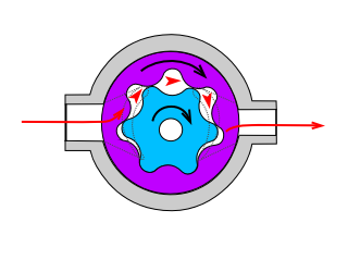
 The most common variations are shown below (the drive gear is shown blue and the idler is shown purple).

An external precision gear pump is usually limited to a maximum working pressure of 210 bars (21,000 kPa) and a maximum speed of 3,000 rpm. Some manufacturers produce gear pumps with higher working pressures and speeds but these types of pumps tend to be noisy and special precautions may have to be made. [3]

Suction and pressure ports need to interface where the gears mesh (shown as dim gray lines in the internal pump images). Some internal gear pumps have an additional, crescent-shaped seal (shown above, right). This crescent functions to keep the gears separated and also reduces eddy currents.

Pump formulas:

Efficiency

Gear pumps are generally very efficient, especially in high pressure applications.

Factors affecting efficiency:

Applications

See also

Related Research Articles

<span class="mw-page-title-main">Pump</span> Device that imparts energy to the fluids by mechanical action

A pump is a device that moves fluids, or sometimes slurries, by mechanical action, typically converted from electrical energy into hydraulic energy.

<span class="mw-page-title-main">Vacuum pump</span> Equipment generating a relative vacuum

A vacuum pump is a type of pump device that draws gas particles from a sealed volume in order to leave behind a partial vacuum. The first vacuum pump was invented in 1650 by Otto von Guericke, and was preceded by the suction pump, which dates to antiquity.

Fluid bearings are bearings in which the load is supported by a thin layer of rapidly moving pressurized liquid or gas between the bearing surfaces. Since there is no contact between the moving parts, there is no sliding friction, allowing fluid bearings to have lower friction, wear and vibration than many other types of bearings. Thus, it is possible for some fluid bearings to have near-zero wear if operated correctly.

<span class="mw-page-title-main">Diaphragm pump</span> Positive displacement pump that uses a reciprocating membrane

A diaphragm pump is a positive displacement pump that uses a combination of the reciprocating action of a rubber, thermoplastic or teflon diaphragm and suitable valves on either side of the diaphragm (check valve, butterfly valves, flap valves, or any other form of shut-off valves) to pump a fluid.

<span class="mw-page-title-main">Fluid power</span> Use of fluids under pressure to generate, control, and transmit power

Fluid power is the use of fluids under pressure to generate, control, and transmit power. Fluid power is conventionally subdivided into hydraulics and pneumatics. Although steam is also a fluid, steam power is usually classified separately from fluid power. Compressed-air and water-pressure systems were once used to transmit power from a central source to industrial users over extended geographic areas; fluid power systems today are usually within a single building or mobile machine.

<span class="mw-page-title-main">Hydraulic machinery</span> Type of machine that uses liquid fluid power to perform work

Hydraulic machines use liquid fluid power to perform work. Heavy construction vehicles are a common example. In this type of machine, hydraulic fluid is pumped to various hydraulic motors and hydraulic cylinders throughout the machine and becomes pressurized according to the resistance present. The fluid is controlled directly or automatically by control valves and distributed through hoses, tubes, or pipes.

<span class="mw-page-title-main">Axial piston pump</span>

An axial piston pump is a positive displacement pump that has a number of pistons in a circular array within a cylinder block. It can be used as a stand-alone pump, a hydraulic motor or an automotive air conditioning compressor.

<span class="mw-page-title-main">Rotary vane pump</span>

A rotary vane pump is a type of positive-displacement pump that consists of vanes mounted to a rotor that rotates inside a cavity. In some cases these vanes can have variable length and/or be tensioned to maintain contact with the walls as the pump rotates.

<span class="mw-page-title-main">Rotary-screw compressor</span> Gas compressor using a rotary positive-displacement mechanism

A rotary-screw compressor is a type of gas compressor, such as an air compressor, that uses a rotary-type positive-displacement mechanism. These compressors are common in industrial applications and replace more traditional piston compressors where larger volumes of compressed gas are needed, e.g. for large refrigeration cycles such as chillers, or for compressed air systems to operate air-driven tools such as jackhammers and impact wrenches. For smaller rotor sizes the inherent leakage in the rotors becomes much more significant, leading to this type of mechanism being less suitable for smaller compressors than piston compressors.

<span class="mw-page-title-main">Gerotor</span>

A gerotor is a positive displacement pump. The name gerotor is derived from "generated rotor". A gerotor unit consists of an inner and outer rotor. The inner rotor has n teeth, while the outer rotor has n+1 teeth; with n defined as a natural number greater than or equal to 2. The axis of the inner rotor is offset from the axis of the outer rotor and both rotors rotate on their respective axes. The geometry of the two rotors partitions the volume between them into n different dynamically-changing volumes. During the assembly's rotation cycle, each of these volumes changes continuously, so any given volume first increases, and then decreases. An increase creates a vacuum. This vacuum creates suction, and hence, this part of the cycle is where the inlet is located. As a volume decreases compression occurs. During this compression period, fluids can be pumped, or, if they are gaseous fluids, compressed.

<span class="mw-page-title-main">Lobe pump</span>

A lobe pump, or rotary lobe pump, is a type of positive displacement pump. It is similar to a gear pump except the lobes are designed to almost meet, rather than touch and turn each other. An early example of a lobe pump is the Roots Blower, patented in 1860 to blow combustion air to melt iron in blast furnaces, but now more commonly used as an engine supercharger.

<span class="mw-page-title-main">Hydraulic motor</span> Machine converting flow into rotation

A hydraulic motor is a mechanical actuator that converts hydraulic pressure and flow into torque and angular displacement (rotation). The hydraulic motor is the rotary counterpart of the hydraulic cylinder as a linear actuator. Most broadly, the category of devices called hydraulic motors has sometimes included those that run on hydropower but in today's terminology the name usually refers more specifically to motors that use hydraulic fluid as part of closed hydraulic circuits in modern hydraulic machinery.

<span class="mw-page-title-main">Hydraulic pump</span> Mechanical power source

A hydraulic pump is a mechanical source of power that converts mechanical power into hydraulic energy. Hydraulic pumps are used in hydraulic drive systems and can be hydrostatic or hydrodynamic. They generate flow with enough power to overcome pressure induced by a load at the pump outlet. When a hydraulic pump operates, it creates a vacuum at the pump inlet, which forces liquid from the reservoir into the inlet line to the pump and by mechanical action delivers this liquid to the pump outlet and forces it into the hydraulic system. Hydrostatic pumps are positive displacement pumps while hydrodynamic pumps can be fixed displacement pumps, in which the displacement cannot be adjusted, or variable displacement pumps, which have a more complicated construction that allows the displacement to be adjusted. Hydrodynamic pumps are more frequent in day-to-day life. Hydrostatic pumps of various types all work on the principle of Pascal's law.

<span class="mw-page-title-main">Oil pump (internal combustion engine)</span> Internal combustion engine part that circulates engine oil under pressure

The oil pump is an internal combustion engine part that circulates engine oil under pressure to the rotating bearings, the sliding pistons and the camshaft of the engine. This lubricates the bearings, allows the use of higher-capacity fluid bearings and also assists in cooling the engine.

A mud pump, is a reciprocating piston/plunger pump designed to circulate drilling fluid under high pressure down the drill string and back up the annulus. A mud pump is an important part of the equipment used for oil well drilling.

A rotodynamic pump is a kinetic machine in which energy is continuously imparted to the pumped fluid by means of a rotating impeller, propeller, or rotor, in contrast to a positive displacement pump in which a fluid is moved by trapping a fixed amount of fluid and forcing the trapped volume into the pump's discharge. Examples of rotodynamic pumps include adding kinetic energy to a fluid such as by using a centrifugal pump to increase fluid velocity or pressure.

PumpLinx is a 3-D computational fluid dynamics (CFD) software developed for the analysis of fluid pumps, motors, compressors, valves, propellers, hydraulic systems, and other fluid devices with rotating or sliding components.

<span class="mw-page-title-main">Marles steering gear</span>

Marles steering gear was an hour-glass-and-roller steering gear for mechanically propelled vehicles invented by British inventor and businessman Henry Marles (1871-1955) who also gave his name to his joint-venture Ransome & Marles a major British ball-bearing manufacturer. Aside from ease of use Marles' steering's great appeal to drivers was its lack of backlash.

<span class="mw-page-title-main">Marine pump</span>

A Marine pump is a pump which is used on board a vessel (ship) or an offshore platform.

The basic function of a pump is to do work on a liquid. It can be used to transport and compress a liquid. In industries heavy-duty pumps are used to move water, chemicals, slurry, food, oil and so on. Depending on their action, pumps are classified into two types — Centrifugal Pumps and Positive Displacement Pumps. While centrifugal pumps impart momentum to the fluid by motion of blades, positive displacement pumps transfer fluid by variation in the size of the pump’s chamber. Centrifugal pumps can be of rotor or propeller types, whereas positive displacement pumps may be gear-based, piston-based, diaphragm-based, etc. As a general rule, centrifugal pumps are used with low viscosity fluids and positive displacement pumps are used with high viscosity fluids.

References

  1. "Welcome to the Hydraulic Institute". Pumps.org. Archived from the original on 2013-06-26. Retrieved 2013-08-18.
  2. Frank Prager, Kepler as inventor, Vistas in Astronomy, Volume 18, 1975, Pages 887-889, https://doi.org/10.1016/0083-6656(75)90184-1.
  3. Pinches, M J (2000). Kempe's Engineers Year-Book, p. 2070. Miller Freeman, Kent. ISBN   0863824420.