
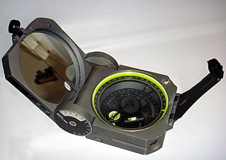
A compass is a device that shows the cardinal directions used for navigation and geographic orientation. It commonly consists of a magnetized needle or other element, such as a compass card or compass rose, which can pivot to align itself with magnetic north. Other methods may be used, including gyroscopes, magnetometers, and GPS receivers.

North is one of the four compass points or cardinal directions. It is the opposite of south and is perpendicular to east and west. North is a noun, adjective, or adverb indicating direction or geography.

Flight instruments are the instruments in the cockpit of an aircraft that provide the pilot with data about the flight situation of that aircraft, such as altitude, airspeed, vertical speed, heading and much more other crucial information in flight. They improve safety by allowing the pilot to fly the aircraft in level flight, and make turns, without a reference outside the aircraft such as the horizon. Visual flight rules (VFR) require an airspeed indicator, an altimeter, and a compass or other suitable magnetic direction indicator. Instrument flight rules (IFR) additionally require a gyroscopic pitch-bank, direction and rate of turn indicator, plus a slip-skid indicator, adjustable altimeter, and a clock. Flight into instrument meteorological conditions (IMC) require radio navigation instruments for precise takeoffs and landings.
In navigation, bearing or azimuth is the horizontal angle between the direction of an object and north or another object. The angle value can be specified in various angular units, such as degrees, mils, or grad. More specifically:
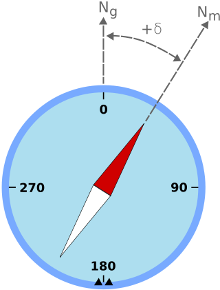
Magnetic declination is the angle between magnetic north and true north at a particular location on the Earth's surface. The angle can change over time due to polar wandering.
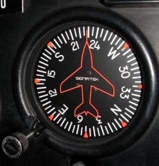
The heading indicator (HI), also known as a directional gyro (DG) or direction indicator (DI), is a flight instrument used in an aircraft to inform the pilot of the aircraft's heading.

The attitude indicator (AI), also known as the gyro horizon or artificial horizon, is a flight instrument that informs the pilot of the aircraft orientation relative to Earth's horizon, and gives an immediate indication of the smallest orientation change. The miniature aircraft and horizon bar mimic the relationship of the aircraft relative to the actual horizon. It is a primary instrument for flight in instrument meteorological conditions.
The basic principles of air navigation are identical to general navigation, which includes the process of planning, recording, and controlling the movement of a craft from one place to another.

An automatic direction finder (ADF) is a marine or aircraft radio-navigation instrument that automatically and continuously displays the relative bearing from the ship or aircraft to a suitable radio station. ADF receivers are normally tuned to aviation or marine NDBs operating in the LW band between 190 – 535 kHz. Like RDF units, most ADF receivers can also receive medium wave (AM) broadcast stations, though these are less reliable for navigational purposes.

Gimbal lock is the loss of one degree of freedom in a multi-dimensional mechanism at certain alignments of the axes. In a three-dimensional three-gimbal mechanism, gimbal lock occurs when the axes of two of the gimbals are driven into a parallel configuration, "locking" the system into rotation in a degenerate two-dimensional space.

Very High Frequency Omnidirectional Range Station (VOR) is a type of short-range VHF radio navigation system for aircraft, enabling aircraft with a VOR receiver to determine the azimuth, referenced to magnetic north, between the aircraft to/from fixed VOR ground radio beacons. VOR and the first DME(1950) system to provide the slant range distance, were developed in the United States as part of a U.S. civil/military programm for Aeronautical Navigation Aids in 1945. Deployment of VOR and DME(1950) began in 1949 by the U.S. CAA. ICAO standardized VOR and DME(1950) in 1950 in ICAO Annex ed.1. Frequencies for the use of VOR are standardized in the very high frequency (VHF) band between 108.00 and 117.95 MHz Chapter 3, Table A. To improve azimuth accuracy of VOR even under difficult siting conditions, Doppler VOR (DVOR) was developed in the 1960s. VOR is according to ICAO rules a primary means navigation system for commercial and general aviation, (D)VOR are gradually decommissioned and replaced by DME-DME RNAV 7.2.3 and satellite based navigation systems such as GPS in the early 21st century. In 2000 there were about 3,000 VOR stations operating around the world, including 1,033 in the US, but by 2013 the number in the US had been reduced to 967. The United States is decommissioning approximately half of its VOR stations and other legacy navigation aids as part of a move to performance-based navigation, while still retaining a "Minimum Operational Network" of VOR stations as a backup to GPS. In 2015, the UK planned to reduce the number of stations from 44 to 19 by 2020.

In navigation, the course of a watercraft or aircraft is the cardinal direction in which the craft is to be steered. The course is to be distinguished from the heading, which is the direction where the watercraft's bow or the aircraft's nose is pointed. The path that a vessel follows is called a track or, in the case of aircraft, ground track. The intended track is a route.

A nephoscope is a 19th-century instrument for measuring the altitude, direction, and velocity of clouds, using transit-time measurement. This is different from a nephometer, which is an instrument used in measuring the amount of cloudiness.
Magnetic deviation is the error induced in a compass by local magnetic fields, which must be allowed for, along with magnetic declination, if accurate bearings are to be calculated.

A helmsman or helm is a person who steers a ship, sailboat, submarine, other type of maritime vessel, airship, or spacecraft. The rank and seniority of the helmsman may vary: on small vessels such as fishing vessels and yachts, the functions of the helmsman are combined with that of the skipper; on larger vessels, there is a separate officer of the watch who is responsible for the safe navigation of the ship and gives orders to the helmsman, who physically steers the ship in accordance with those orders.

Diver navigation, termed "underwater navigation" by scuba divers, is a set of techniques—including observing natural features, the use of a compass, and surface observations—that divers use to navigate underwater. Free-divers do not spend enough time underwater for navigation to be important, and surface supplied divers are limited in the distance they can travel by the length of their umbilicals and are usually directed from the surface control point. On those occasions when they need to navigate they can use the same methods used by scuba divers.

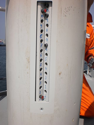
Magnetic dip, dip angle, or magnetic inclination is the angle made with the horizontal by Earth's magnetic field lines. This angle varies at different points on Earth's surface. Positive values of inclination indicate that the magnetic field of Earth is pointing downward, into Earth, at the point of measurement, and negative values indicate that it is pointing upward. The dip angle is in principle the angle made by the needle of a vertically held compass, though in practice ordinary compass needles may be weighted against dip or may be unable to move freely in the correct plane. The value can be measured more reliably with a special instrument typically known as a dip circle.

The Earth inductor compass is a compass that determines directions using the principle of electromagnetic induction, with the Earth's magnetic field acting as the induction field for an electric generator. The electrical output of the generator will vary depending on its orientation with respect to the Earth's magnetic field. This variation in the generated voltage is measured, allowing the Earth inductor compass to determine direction.

The Course Setting Bomb Sight (CSBS) is the canonical vector bombsight, the first practical system for properly accounting for the effects of wind when dropping bombs. It is also widely referred to as the Wimperis sight after its inventor, Harry Wimperis.

The compass is a magnetometer used for navigation and orientation that shows direction in regards to the geographic cardinal points. The structure of a compass consists of the compass rose, which displays the four main directions on it: East (E), South (S), West (W) and North (N). The angle increases in the clockwise position. North corresponds to 0°, so east is 90°, south is 180° and west is 270°.

