Hot swapping is the replacement or addition of components to a computer system without stopping, shutting down, or rebooting the system.[1]Hot plugging describes only the addition of components to a running computer system.[2] Components which have such functionality are said to be hot-swappable or hot-pluggable; likewise, components which do not are cold-swappable or cold-pluggable. Although the broader concept of hot swapping can apply to electrical or mechanical systems, it is usually mentioned in the context of computer systems.
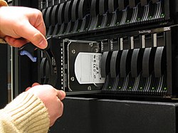
Most desktop computer hardware, such as CPUs and memory, are only cold-pluggable. However, it is common for mid to high-end servers and mainframes to feature hot-swappable capability for hardware components, such as CPU, memory, PCIe, SATA and SAS drives.
Most smartphones and tablets with tray-loading holders can interchange SIM cards without powering down the system.
Dedicated digital cameras and camcorders usually have readily accessible memory card and battery compartments for quick changing with only minimal interruption of operation. Batteries can be cycled through by recharging reserve batteries externally while unused. Many cameras and camcorders feature an internal memory to allow capturing when no memory card is inserted.
Rationale
Hot swapping is primarily used whenever it is desirable to change the configuration or repair a working system without interrupting its operation.[3] A typical example of needing to keep a system running at all times is in the case of a server, a computer that provides access to essential data and applications needed by other computers called clients. At other times, hot swapping is implemented simply to avoid the delay and nuisance of shutting down and then restarting a device, such as in the case of charging a smartphone.
Hot swapping is used to add or remove peripherals or components and to replace faulty modules without interrupting equipment operation. For example, a machine may have dual hot-swappable power supplies, each adequate enough to power the machine on its own. If one of those power supplies breaks and shuts down, the machine will not shut down, as it will draw power from the other, functional power supply. The faulty power supply can be replaced during operation of the machine, eventually bringing the machine back to a state of redundancy. In the context of servers, important expansion cards, such as disk controllers or host adapters, may be designed with specialized redundancy features in order for these to be replaceable without necessitating interruption of server operation.
Another use case of hot swapping is to enable faster data synchronization between two devices by not having to power down either device before connecting them together. For example, plugging an iPhone to a Mac computer via a USB cable to synchronize data between them does not require powering down either the iPhone or the Mac and waiting for them to restart.[4] For even more convenience, data synchronization can be configured to start automatically without user input. It is also possible to interrupt the data synchronization at any time simply through unplugging the devices, although it's not recommended to do so until instructed to avoid data corruption.
Mechanical and electrical design considerations
Machines that support hot swapping need to be able to modify their operation for the changed configuration, either automatically on detecting the change, or by user intervention. All electrical and mechanical connections associated with hot-swapping must be designed so that neither the equipment nor the user can be harmed while hot-swapping. Other components in the system must be designed so that the removal of a hot-swappable component does not interrupt operation.
Protection against electrostatic damage
Protective covering plates, shields, or bezels may be used on either the removable components or the main device itself to prevent operator contact with live powered circuitry, to provide antistatic protection for components being added or removed, or to prevent the removable components from accidentally touching and shorting out the powered components in the operating device.
Additional guide slots, pins, notches, or holes may be used to aid in proper insertion of a component between other live components, while mechanical engagement latches, handles, or levers may be used to assist in proper insertion and removal of devices that either require large amounts of force to connect or disconnect, or to assist in the proper mating and holding together of power and communications connectors.
Component shutdown procedure before unplugging
Some implementations require a component shutdown procedure prior to removal. This usually results in a simpler design, but such devices are not robust in the case of component failure. In such cases, if a component is removed while it is being used, the operations to that device fail and the user is responsible for retrying if necessary. In practice, this can be an advantageous trade-off for certain designs where cost matters more than reliability.
More complex implementations may recommend but do not require that the component be shut down. In the suboptimal case a component is removed without being shut down, these implementations usually have sufficient redundancy to allow essential operation to continue. In these systems hot swap is normally used for regular maintenance to the computer, or to replace a broken component.
Most modern hot-swap methods use a specialized connector with staggered pins, so that certain pins are certain to be connected before others. Most staggered-pin designs have ground pins longer than the others, ensuring that no sensitive circuitry is connected before there is a reliable system ground. The other pins may all be the same length, but in some cases three pin lengths are used so that the incoming device is grounded first, data lines connected second, and power applied third, in rapid succession as the device is inserted. Pins of the same nominal length do not necessarily make contact at exactly the same time due to mechanical tolerances, and angling of the connector when inserted.
At one time staggered pins were thought to be an expensive solution,[citation needed] but many contemporary connector families now come with staggered pins as standard; for example, they are used on all modern serial SCSI disk-drives. Specialized hot-plug power connector pins are now commercially available with repeatable DC current interruption ratings of up to 16A. Printed circuit boards are made with staggered edge-fingers for direct hot-plugging into a backplane connector.
Although the speed of plugging cannot be controlled precisely, practical considerations will provide limits that can be used to determine worst-case conditions. For a typical staggered pin design where the length difference is 0.5mm, the elapsed time between long and short pin contact is between 25ms and 250ms. It is quite practical to design hot-swap circuits that can operate at that speed.
Hot-swap connector corner pins
As long as the hot-swap connector is sufficiently rigid, one of the four corner pins will always be the first to engage. For a typical two-row connector arrangement this provides four first-to-make corner pins that are usually used for grounds. Other pins near the corners can be used for functions that would also benefit from this effect, for example sensing when the connector is fully seated. This diagram illustrates good practice where the grounds are in the corners and the power pins are near the center. Two sense pins are located in opposite corners so that fully seated detection is confirmed only when both of them are in contact with the slot. The remaining pins are used for all the other data signals.
Power electronics
The DC power supplies to a hot-swap component are usually pre-charged by dedicated long pins that make contact before the main power pins. These pre-charge pins are protected by a circuit that limits the inrush current to an acceptable value that cannot damage the pins nor disturb the supply voltage to adjacent slots. The pre-charge circuit might be a simple series resistor, a negative temperature coefficient (NTC) resistor, or a current-limiter circuit. Further protection can be provided by a "soft-start" circuit that provides a managed ramp-up of the internal DC supply voltages within the component.
A typical sequence for a hot-swap component being plugged into a slot could be as follows:
Long ground pins make contact; basic electrical safety and ESD protection becomes available.
Long (or medium) pre-charge pins make contact; decoupling capacitors start to charge up.
Real time delay of tens of milliseconds.
Short power/signal pins make contact.
Connector becomes fully seated; power-on reset signal asserted within component
Soft-start circuit starts to apply power to the component.
Hot-swap power circuits can now be purchased commercially in specially designed ASICs called hot-swap power managers (HSPMs).
Signal electronics
Circuitry attached to signal pins in a hot-swap component should include some protection against electrostatic discharge (ESD). This usually takes the form of clamp diodes to ground and to the DC power supply voltage. ESD effects can be reduced by careful design of the mechanical package around the hot-swap component, perhaps by coating it with a thin film of conductive material.
Particular care must be taken when designing systems with bussed signals which are wired to more than one hot-swap component. When a hot-swap component is inserted its input and output signal pins will represent a temporary short-circuit to ground. This can cause unwanted ground-level pulses on the signals which can disturb the operation of other hot-swap components in the system. This was a problem for early parallel SCSI disk-drives. One common design solution is to protect bussed signal pins with series diodes or resistors. CMOS buffer devices are now available with specialized inputs and outputs that minimize disturbance of bussed signals during the hot-swap operation. If all else fails, another solution is to quiesce the operation of all components during the hot-swap operation.
Applications
This section needs expansionwith: Major uses including server components and USB peripherals (currently mentioned in lead but not discussed in body). Other uses (not currently mentioned but shouldn't be hard to find reliable sources) include uninterruptible power supply batteries, electric car batteries.. You can help by adding to it. (April 2022)
Radio transmitters
Modern day radio transmitters (and some TV transmitters as well) use high power RF transistor power modules instead of vacuum tubes. Hot swapping power modules is not a new technology, as many of the radio transmitters manufactured in the 1930s were capable of having power tubes swapped out while the transmitter was running—but this feature was not universally adopted due to the introduction of more reliable high power tubes.
In the mid-1990s, several radio transmitter manufactures in the US started offering swappable high power RF transistor modules.
There was no industry standard for the design of the swappable power modules at the time.
Early module designs had only limited patent restrictions.
By the early 2000s, many transmitter models were available that used many different kinds of power modules.
The reintroduction of power modules has been good for the radio transmitter industry, as it has fostered innovation. Modular transmitters have proven to be more reliable than tube transmitters, when the transmitter is properly chosen for the conditions at the transmitting site.
Power limitations:
Lowest power modular transmitter: generally 1.0kW, using 600W modules.
Highest power modular transmitter: 1.0MW (for LW, MW).
Highest power modular transmitter: 45kW (FM, TV).
Gaming
Although most contemporary video game systems can interchange games and multimedia (e.g. Blu-rays) without powering down the system, older generations of systems varied in their support of hot-swapping capabilities. For example, whereas the Sony PlayStation and PlayStation 2 could eject a game disc with the system powered on, the Nintendo Game Boy Advance and the Nintendo 64 would freeze up and could potentially become corrupt if the game cartridge was removed with the power on. Manufacturers specifically warned against such practices in the owner's manual or on the game cartridge.[5] It was supposedly for this reason that Stop 'N' Swop was taken out of the Banjo-Kazooie series and Donkey Kong 64. With the Sega Genesis/Mega Drive system, it was sometimes possible to apply cheats (such as a player having infinite lives) and other temporary software alterations to games by hot swapping cartridges, even though the cartridges were not designed to be hot swappable.[6]
Hot-swappable keyboards enable changing the switches without having to disassemble the keyboard.[7] On standard mechanical-switch keyboards, the switch is directly soldered to the PCB. Hot-swappable keyboards instead have a socket in its place that allows the switch to be freely replaced without re-soldering.[8]
Hot-swappable keyboards are becoming increasingly common[citation needed], and it has become somewhat of a standard[citation needed] in most enthusiast keyboards as well as keyboard components to support hot swapping.[7] They can be found in a variety of sizes and layouts, including more specialized ergonomic layouts.
Hot swapping can also refer to the ability to alter the running code of a program without needing to interrupt its execution. Interactive programming is a programming paradigm that makes extensive use of hot swapping, so the programming activity becomes part of the program flow itself.
Hot swapping is the central method in live coding, where programming is an integral part of the runtime process. In general, all programming languages used in live coding, such as SuperCollider, TidalCycles, or Extempore support hot swapping.
Some web-based frameworks, such as Django, support detecting module changes and reloading them on the fly. However, although the same as hotswapping for most intents and purposes, this is technically just a cache purge, triggered by a new file. This does not apply to markup and programming languages such as HTML and PHP respectively, in the general case, as these files are normally reinterpreted on each use by default. There are a few CMSes and other PHP-based frameworks (such as Drupal) that employ caching, however. In these cases, similar abilities and exceptions apply.
Hot swapping also facilitates developing systems where large amounts of data are being processed, as in entire genomes in bioinformatics algorithms.[11]
Trademarks
The term "HOT PLUG" was registered as a trademark in the United States in November 1992 to Core International, Inc., and cancelled in May 1999.[12]
↑ Hennessy, John L.; Patterson, David A. (2002). Computer Architecture: A Quantitative Approach. The Morgan Kaufmann Series in Computer Architecture and Design. Morgan Kaufmann. p.707. ISBN9780080502526.
↑ Tabisz, W.A.; Jovanovic, M.M.; Lee, F.C. (23–27 February 1992). Present and future of distributed power systems. Seventh Annual Applied Power Electronics Conference and Exposition, 1992. APEC '92. Conference Proceedings 1992. IEEE. pp.11–12. doi:10.1109/APEC.1992.228437. ISBN0-7803-0485-3. A properly designed parallel configuration allows the on-line replacement (hot-swapping) of defective modules. This provides means for non-interrupting maintenance and repair, a very desirable feature in high-reliability systems operating in a continuous fashion.
This page is based on this Wikipedia article Text is available under the CC BY-SA 4.0 license; additional terms may apply. Images, videos and audio are available under their respective licenses.