In computer programming, assembly language, often referred to simply as assembly and commonly abbreviated as ASM or asm, is any low-level programming language with a very strong correspondence between the instructions in the language and the architecture's machine code instructions. Assembly language usually has one statement per machine instruction (1:1), but constants, comments, assembler directives, symbolic labels of, e.g., memory locations, registers, and macros are generally also supported.

In computing, BIOS is firmware used to provide runtime services for operating systems and programs and to perform hardware initialization during the booting process. The BIOS firmware comes pre-installed on an IBM PC or IBM PC compatible's system board and exists in some UEFI-based systems to maintain compatibility with operating systems that do not support UEFI native operation. The name originates from the Basic Input/Output System used in the CP/M operating system in 1975. The BIOS originally proprietary to the IBM PC has been reverse engineered by some companies looking to create compatible systems. The interface of that original system serves as a de facto standard.

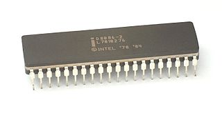
x86 is a family of complex instruction set computer (CISC) instruction set architectures initially developed by Intel based on the 8086 microprocessor and its 8088 variant. The 8086 was introduced in 1978 as a fully 16-bit extension of 8-bit Intel's 8080 microprocessor, with memory segmentation as a solution for addressing more memory than can be covered by a plain 16-bit address. The term "x86" came into being because the names of several successors to Intel's 8086 processor end in "86", including the 80186, 80286, 80386 and 80486. Colloquially, their names were "186", "286", "386" and "486".

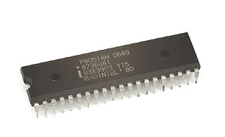
The Intel MCS-51 is a single chip microcontroller (MCU) series developed by Intel in 1980 for use in embedded systems. The architect of the Intel MCS-51 instruction set was John H. Wharton. Intel's original versions were popular in the 1980s and early 1990s, and enhanced binary compatible derivatives remain popular today. It is a complex instruction set computer, but also has some of the features of RISC architectures, such as a large register set and register windows, and has separate memory spaces for program instructions and data.
x86 memory segmentation refers to the implementation of memory segmentation in the Intel x86 computer instruction set architecture. Segmentation was introduced on the Intel 8086 in 1978 as a way to allow programs to address more than 64 KB (65,536 bytes) of memory. The Intel 80286 introduced a second version of segmentation in 1982 that added support for virtual memory and memory protection. At this point the original mode was renamed to real mode, and the new version was named protected mode. The x86-64 architecture, introduced in 2003, has largely dropped support for segmentation in 64-bit mode.
x86 assembly language is the name for the family of assembly languages which provide some level of backward compatibility with CPUs back to the Intel 8008 microprocessor, which was launched in April 1972. It is used to produce object code for the x86 class of processors.

The A20, or address line 20, is one of the electrical lines that make up the system bus of an x86-based computer system. The A20 line in particular is used to transmit the 21st bit on the address bus.
In computer engineering, Halt and Catch Fire, known by the assembly language mnemonic HCF, is an idiom referring to a computer machine code instruction that causes the computer's central processing unit (CPU) to cease meaningful operation, typically requiring a restart of the computer. It originally referred to a fictitious instruction in IBM System/360 computers, making a joke about its numerous non-obvious instruction mnemonics.

A general protection fault (GPF) in the x86 instruction set architectures (ISAs) is a fault initiated by ISA-defined protection mechanisms in response to an access violation caused by some running code, either in the kernel or a user program. The mechanism is first described in Intel manuals and datasheets for the Intel 80286 CPU, which was introduced in 1983; it is also described in section 9.8.13 in the Intel 80386 programmer's reference manual from 1986. A general protection fault is implemented as an interrupt. Some operating systems may also classify some exceptions not related to access violations, such as illegal opcode exceptions, as general protection faults, even though they have nothing to do with memory protection. If a CPU detects a protection violation, it stops executing the code and sends a GPF interrupt. In most cases, the operating system removes the failing process from the execution queue, signals the user, and continues executing other processes. If, however, the operating system fails to catch the general protection fault, i.e. another protection violation occurs before the operating system returns from the previous GPF interrupt, the CPU signals a double fault, stopping the operating system. If yet another failure occurs, the CPU is unable to recover; since 80286, the CPU enters a special halt state called "Shutdown", which can only be exited through a hardware reset. The IBM PC AT, the first PC-compatible system to contain an 80286, has hardware that detects the Shutdown state and automatically resets the CPU when it occurs. All descendants of the PC AT do the same, so in a PC, a triple fault causes an immediate system reset.
The x86 instruction set refers to the set of instructions that x86-compatible microprocessors support. The instructions are usually part of an executable program, often stored as a computer file and executed on the processor.
BIOS implementations provide interrupts that can be invoked by operating systems and application programs to use the facilities of the firmware on IBM PC compatible computers. Traditionally, BIOS calls are mainly used by DOS programs and some other software such as boot loaders. BIOS runs in the real address mode of the x86 CPU, so programs that call BIOS either must also run in real mode or must switch from protected mode to real mode before calling BIOS and then switching back again. For this reason, modern operating systems that use the CPU in Protected mode or Long mode generally do not use the BIOS interrupt calls to support system functions, although they use the BIOS interrupt calls to probe and initialize hardware during booting. Real mode has the 1MB memory limitation, modern boot loaders use the unreal mode or protected mode to access up to 4GB memory.
In computing, the reset vector is the default location a central processing unit will go to find the first instruction it will execute after a reset. The reset vector is a pointer or address, where the CPU should always begin as soon as it is able to execute instructions. The address is in a section of non-volatile memory initialized to contain instructions to start the operation of the CPU, as the first step in the process of booting the system containing the CPU.
In computer programming, the term hooking covers a range of techniques used to alter or augment the behaviour of an operating system, of applications, or of other software components by intercepting function calls or messages or events passed between software components. Code that handles such intercepted function calls, events or messages is called a hook.
INT 13h is shorthand for BIOS interrupt call 13hex, the 20th interrupt vector in an x86-based computer system. The BIOS typically sets up a real mode interrupt handler at this vector that provides sector-based hard disk and floppy disk read and write services using cylinder-head-sector (CHS) addressing. Modern PC BIOSes also include INT 13h extension functions, originated by IBM and Microsoft in 1992, that provide those same disk access services using 64-bit LBA addressing; with minor additions, these were quasi-standardized by Phoenix Technologies and others as the EDD BIOS extensions.
The interrupt descriptor table (IDT) is a data structure used by the x86 architecture to implement an interrupt vector table. The IDT is used by the processor to determine the correct response to interrupts and exceptions.
On the x86 architecture, a debug register is a register used by a processor for program debugging. There are six debug registers, named DR0...DR7, with DR4 and DR5 as obsolete synonyms for DR6 and DR7. The debug registers allow programmers to selectively enable various debug conditions associated with a set of four debug addresses. Two of these registers are used to control debug features. These registers are accessed by variants of the MOV instruction. A debug register may be either the source operand or destination operand. The debug registers are privileged resources; the MOV instructions that access them can only be executed at privilege level zero. An attempt to read or write the debug registers when executing at any other privilege level causes a general protection fault.
In the x86 computer architecture, HLT (halt) is an assembly language instruction which halts the central processing unit (CPU) until the next external interrupt is fired. Interrupts are signals sent by hardware devices to the CPU alerting it that an event occurred to which it should react. For example, hardware timers send interrupts to the CPU at regular intervals.
The XOP instruction set, announced by AMD on May 1, 2009, is an extension to the 128-bit SSE core instructions in the x86 and AMD64 instruction set for the Bulldozer processor core, which was released on October 12, 2011. However AMD removed support for XOP from Zen (microarchitecture) onward.
The VEX prefix and VEX coding scheme are an extension to the IA-32 and x86-64 instruction set architecture for microprocessors from Intel, AMD and others.
A master boot record (MBR) is a type of boot sector in the first few blocks of partitioned computer mass storage devices like fixed disks or removable drives intended for use with IBM PC-compatible systems and beyond. The concept of MBRs was publicly introduced in 1983 with PC DOS 2.0.


