A measurement system consists of a sensor, to input the physical parameter that is of interest, and an output to a medium that is suitable for reading by the system that needs to know the value of the parameter. (This could be a device to convert the temperature of the surrounding air or water into the visually readable height of a column of mercury in a small tube, for example; but the conversion could also be made to an electronic encoding of the parameter, for reading by a computer system.)
The integral linearity is then a measure of the fidelity of the conversion that is performed by the measuring system. It is the relation of the output to the input over a range expressed as a percentage of the full-scale measurements. Integral linearity is a measure of the device's deviation from ideal linear behaviour.
The most common denotation of integral linearity is independent linearity.
In the context of a digital-to-analog converter (DAC) or an analog-to-digital converter (ADC), independent linearity is fitted to minimize the deviation with respect to the ideal behaviour with no constraints. Other types of integral linearity place constraints on the symmetry or end points of the linear fit with respect to the actual data.[1][2]
In the case of position sensors, two general types exist. Differences between the two regarding independent linearity essentially relate to the type of mechanical interface - linear or rotary. For rotary position sensors, as a shaft (or in the case of magnetic sensors, a magnet) is turned over a defined mechanical range in a direction causing an increasing response, an output voltage changes from a minimum to maximum value. The variation from an ideal linear relationship as this device is changed from minimum to maximum range end-points is the independent linearity error. It is measured in a practical sense as deviation of output voltage as a percentage of input voltage with the maximum value as the range is traversed, usually being referred to in a device's specifications. The same description holds for linear position sensors except that a straight rod (or magnet) is moved along the length of the sensor or as it extends from the end of a linear position sensor.[3]
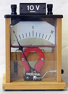
A voltmeter is an instrument used for measuring electric potential difference between two points in an electric circuit. It is connected in parallel. It usually has a high resistance so that it takes negligible current from the circuit.
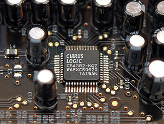
In electronics, an analog-to-digital converter is a system that converts an analog signal, such as a sound picked up by a microphone or light entering a digital camera, into a digital signal. An ADC may also provide an isolated measurement such as an electronic device that converts an input analog voltage or current to a digital number representing the magnitude of the voltage or current. Typically the digital output is a two's complement binary number that is proportional to the input, but there are other possibilities.
A multimeter or a multitester, also known as a VOM (volt-ohm-milliammeter), is an electronic measuring instrument that combines several measurement functions in one unit. A typical multimeter can measure voltage, current, and resistance. Analog multimeters use a microammeter with a moving pointer to display readings. Digital multimeters have a numeric display, and may also show a graphical bar representing the measured value. Digital multimeters have rendered analog multimeters obsolescent, because they are now lower cost, higher precision, and more physically robust.
A potentiometer is a three-terminal resistor with a sliding or rotating contact that forms an adjustable voltage divider. If only two terminals are used, one end and the wiper, it acts as a variable resistor or rheostat.
Linearity is the property of a mathematical relationship (function) that can be graphically represented as a straight line. Linearity is closely related to proportionality. Examples in physics include the linear relationship of voltage and current in an electrical conductor, and the relationship of mass and weight. By contrast, more complicated relationships are nonlinear.
In electronics, a digital-to-analog converter is a system that converts a digital signal into an analog signal. An analog-to-digital converter (ADC) performs the reverse function.
In the broadest definition, a sensor is a device, module, machine, or subsystem whose purpose is to detect events or changes in its environment and send the information to other electronics, frequently a computer processor. A sensor is always used with other electronics.
A Hall-effect sensor is a device to measure the magnitude of a magnetic field. Its output voltage is directly proportional to the magnetic field strength through it.
In electronics, a voltage divider is a passive linear circuit that produces an output voltage (Vout) that is a fraction of its input voltage (Vin). Voltage division is the result of distributing the input voltage among the components of the divider. A simple example of a voltage divider is two resistors connected in series, with the input voltage applied across the resistor pair and the output voltage emerging from the connection between them.
A voltage regulator is a system designed to automatically maintain a constant voltage. A voltage regulator may use a simple feed-forward design or may include negative feedback. It may use an electromechanical mechanism, or electronic components. Depending on the design, it may be used to regulate one or more AC or DC voltages.
The linear variable differential transformer (LVDT) is a type of electrical transformer used for measuring linear displacement (position). A counterpart to this device that is used for measuring rotary displacement is called a rotary variable differential transformer (RVDT).
An integrator in measurement and control applications is an element whose output signal is the time integral of its input signal. It accumulates the input quantity over a defined time to produce a representative output.
Delta-sigma modulation is a method for encoding analog signals into digital signals as found in an analog-to-digital converter (ADC). It is also used to convert high bit-count, low-frequency digital signals into lower bit-count, higher-frequency digital signals as part of the process to convert digital signals into analog as part of a digital-to-analog converter (DAC).
In electronics, signal conditioning is the manipulation of an analog signal in such a way that it meets the requirements of the next stage for further processing.
Differential nonlinearity is a commonly used measure of performance in digital-to-analog (DAC) and analog-to-digital (ADC) converters. It is a term describing the deviation between two analog values corresponding to adjacent input digital values. It is an important specification for measuring error in a digital-to-analog converter (DAC); the accuracy of a DAC is mainly determined by this specification. Ideally, any two adjacent digital codes correspond to output analog voltages that are exactly one Least Significant Bit (LSB) apart. Differential non-linearity is a measure of the worst-case deviation from the ideal 1 LSB step. For example, a DAC with a 1.5 LSB output change for a 1 LSB digital code change exhibits 1⁄2 LSB differential non-linearity. Differential non-linearity may be expressed in fractional bits or as a percentage of full scale. A differential non-linearity greater than 1 LSB may lead to a non-monotonic transfer function in a DAC. It is also known as a missing code.
Integral nonlinearity is a commonly used measure of performance in digital-to-analog (DAC) and analog-to-digital (ADC) converters. In DACs, it is a measure of the deviation between the ideal output value and the actual measured output value for a certain input code. In ADCs, it is the deviation between the ideal input threshold value and the measured threshold level of a certain output code. This measurement is performed after offset and gain errors have been compensated.
An integrating ADC is a type of analog-to-digital converter that converts an unknown input voltage into a digital representation through the use of an integrator. In its basic implementation, the dual-slope converter, the unknown input voltage is applied to the input of the integrator and allowed to ramp for a fixed time period. Then a known reference voltage of opposite polarity is applied to the integrator and is allowed to ramp until the integrator output returns to zero. The input voltage is computed as a function of the reference voltage, the constant run-up time period, and the measured run-down time period. The run-down time measurement is usually made in units of the converter's clock, so longer integration times allow for higher resolutions. Likewise, the speed of the converter can be improved by sacrificing resolution.
Most of the terms listed in Wikipedia glossaries are already defined and explained within Wikipedia itself. However, glossaries like this one are useful for looking up, comparing and reviewing large numbers of terms together. You can help enhance this page by adding new terms or writing definitions for existing ones.
A voltage-controlled resistor (VCR) is a three-terminal active device with one input port and two output ports. The input-port voltage controls the value of the resistor between the output ports. VCRs are most often built with field-effect transistors (FETs). Two types of FETs are often used: the JFET and the MOSFET. There are both floating voltage-controlled resistors and grounded voltage-controlled resistors. Floating VCRs can be placed between two passive or active components. Grounded VCRs, the more common and less complicated design, require that one port of the voltage-controlled resistor be grounded.
This glossary of industrial automation is a list of definitions of terms and illustrations related specifically to the field of industrial automation. For a more general view on electric engineering, see Glossary of electrical and electronics engineering. For terms related to engineering in general, see Glossary of engineering.
This page is based on this Wikipedia article Text is available under the CC BY-SA 4.0 license; additional terms may apply. Images, videos and audio are available under their respective licenses.