Isolation amplifier

Last updated

Isolation amplifiers are a form of differential amplifier that allow measurement of small signals in the presence of a high common mode voltage by providing electrical isolation and an electrical safety barrier. They protect data acquisition components from common mode voltages, which are potential differences between instrument ground and signal ground. Instruments that are applied in the presence of a common mode voltage without an isolation barrier allow ground currents to circulate, leading in the best case to a noisy representation of the signal under investigation. In the worst case, assuming that the magnitude of common mode voltage or current is sufficient, instrument destruction is likely. Isolation amplifiers are used in medical instruments to ensure isolation of a patient from power supply leakage current. [1]

Contents

Amplifiers with an isolation barrier allow the front-end of the amplifier to float with respect to common mode voltage to the limit of the barrier's breakdown voltage, which is often 1,000 volts or more. This action protects the amplifier and the instrument connected to it, while still allowing a reasonably accurate measurement.

These amplifiers are also used for amplifying low-level signals in multi-channel applications. They can also eliminate measurement errors caused by ground loops. Amplifiers with internal transformers eliminate external isolated power supply. They are usually used as analogue interfaces between systems with separated grounds.

Isolation amplifiers may include isolated power supplies for both the input and output stages, or may use external power supplies on each isolated portion. [1]

Concepts

Signal source components

All signal sources are a composite of normal and common mode voltages Signal source components.gif
All signal sources are a composite of normal and common mode voltages

All signal sources are a composite of two major components. The normal mode component (VNM) represents the signal of interest and is the voltage that is applied directly across the inputs of the amplifier. The common mode component (VCM) represents the difference in potential between the low side of the normal mode component and the ground of the amplifier that is used to measure the signal of interest (the normal mode voltage).

In many measurement situations the common mode component is irrelevantly low, but rarely zero. Common mode components of only a few millivolts are frequently encountered and largely and successfully ignored, especially when the normal mode component is orders of magnitude larger.

The first indicator that common mode voltage magnitude is competing with the normal mode component is a noisy reproduction of the latter at the amplifier's output. Such a situation does not usually define the need for an isolation amplifier, but rather a differential amplifier. Since the common mode component appears simultaneously and in phase on both amplifier inputs, the differential amplifier, within the limits of the amplifier's design, can reject it.

However, if the sum of the normal mode and common mode voltages exceeds either the differential amplifier's common mode range, or maximum range without damage then the need for an isolation amplifier is firmly established.

Operating principles

Isolation amplifiers are commercially available as hybrid integrated circuits made by several manufacturers. There are three methods of providing isolation.

A transformer-isolated amplifier relies on transformer coupling of a high-frequency carrier signal between input and output. Some models also include a transformer-isolated power supply, that may also be used to power external signal processing devices on the isolated side of the system. The bandwidth available depends on the model and may range from 2 to 20 kHz. The isolation amplifier contains a voltage-to-frequency converter connected through a transformer to a frequency-to-voltage converter. The isolation between input and output is provided by the insulation on the transformer windings.

An optically isolated amplifier modulates current through an LED optocoupler. The linearity is improved by using a second optocoupler within a feedback loop. Some devices provide up to 60 kHz bandwidth. Galvanic isolation is provided by the conversion of electric current to photonic flux through the space between the LED and the detector, regardless of the intervening medium.

A third strategy is to use small capacitors to couple a modulated high-frequency carrier; the capacitors can stand off large DC or power frequency AC voltages but provide coupling for the much higher frequency carrier signal. Some models on this principle can stand off 3.5 kilovolts and provide up to 70 kHz bandwidth. [1]

Isolation amplifier usage

Isolation amplifiers are used to allow measurement of small signals in the presence of a high common mode voltage. The capacity of an isolation amplifier is a function of two key isolation amplifier specifications:

  • The amplifier’s isolation breakdown voltage, which defines the absolute maximum common mode voltage that it will tolerate without damage. Specifications of 1,000 volts and more are common.
  • The amplifier’s common mode rejection ratio (CMRR). The CMRR specification defines the degree to which the common mode voltage will disrupt the normal mode component measurement, and therefore affect measurement accuracy.

The frequency of the common mode voltage can adversely affect performance. Higher frequency common mode voltages create difficulty for many isolation amplifiers due to the parasitic capacitance of the isolation barrier. This capacitance appears as a low impedance to higher frequency signals, and allows the common mode voltage to essentially blow past the barrier and interfere with measurements, or even damage the amplifier. However, most common mode voltages are a composite of line voltages, so frequencies generally remain in the 50 to 60 Hz region with some harmonic content, well within the rejection range of most isolation amplifiers.

Differential amplifiers

A non-isolated differential amplifier does not provide isolation between input and output circuits. They share a power supply and a DC path can exist between input and output. A non-isolated differential amplifier can only withstand common-mode voltages up to the power supply voltage.

Similar to the instrumentation amplifier, isolation amplifiers have fixed differential gain over a wide range of frequencies, high input impedance and low output impedance.

Amplifier selection guidelines

Instrumentation amplifiers can be classified into four broad categories, organized from least to most costly:

  • Single-ended. An unbalanced input, non-isolated. Suitable for measurements where common mode voltages are zero, or extremely small. Very inexpensive.
  • Differential. A balanced input, non-isolated. Suitable for measurements where the sum of common mode and normal mode voltages remains within the measurement range of the amplifier.
  • Single-ended, floating common. An isolated and quasi-balanced input (the floating common is typically connected to the (-) input of a differential amplifier). Suitable for off-ground measurements up to the breakdown voltage of the isolation barrier, and exhibits very good common mode rejection (100 db typical).
  • Differential, floating common. An isolated and balanced input. Suitable for off-ground measurements to the breakdown voltage of the isolation barrier, and exhibits superb common mode rejection (>120 db).

For most industrial applications that require isolation, the single-ended floating design provides the best price/performance.

There are also two broad classifications of isolation amplifiers that should be considered in tandem with the application:

  • Amplifiers providing input-to-output isolation without channel-to-channel isolation. This is a less expensive form of isolation that offers only one isolation barrier for a multi-channel instrument. Although the commons of each channel are isolated from power ground by the input-to-output isolation barrier, they are not isolated from each other. Therefore a common mode voltage on one will attempt to float all the others, sometimes with disastrous results. This form of isolation is suitable only when it is certain that there is only one common mode voltage that is equally applied to all channels.
  • Amplifiers providing both input-to-output and channel-to-channel isolation. This is the purest form of isolation, and the option that should be considered for nearly all applications. Multi-channel instruments that employ it are immune to inconsistent common mode voltages on any combination of channels within the limits of the amplifiers.

Typical application

Stacked voltage cell measurements

Stacked voltage cell measurements illustrate the need for an isolation amplifier. Stacked cell application.gif
Stacked voltage cell measurements illustrate the need for an isolation amplifier.

Stacked voltage cell measurements are common with the growing popularity of solar cells and fuel cells. In this application the technician wants to profile the performance of individual series-connected voltages cells, but the need for an isolated amplifier is often overlooked. Each voltage cell (the normal mode voltage) is removed from ground by an amount equal to the sum of the voltage cells below it (the common mode voltage). Unless the amplifiers used to measure individual cell voltages are allowed to float at a level equal to the common mode voltage, measurements are not likely to be accurate for any but the first cell in the string where the common mode voltage is zero.

A non-isolated differential amplifier can be used but it will have a rated maximum common mode voltage that cannot be exceeded while maintaining accuracy.

Related Research Articles

<span class="mw-page-title-main">Amplifier</span> Electronic device/component that increases the strength of a signal

An amplifier, electronic amplifier or (informally) amp is an electronic device that can increase the magnitude of a signal. It is a two-port electronic circuit that uses electric power from a power supply to increase the amplitude of a signal applied to its input terminals, producing a proportionally greater amplitude signal at its output. The amount of amplification provided by an amplifier is measured by its gain: the ratio of output voltage, current, or power to input. An amplifier is defined as a circuit that has a power gain greater than one.

<span class="mw-page-title-main">Operational amplifier</span> High-gain voltage amplifier with a differential input

An operational amplifier is a DC-coupled high-gain electronic voltage amplifier with a differential input and, usually, a single-ended output. In this configuration, an op amp produces an output potential that is typically 100,000 times larger than the potential difference between its input terminals. The operational amplifier traces its origin and name to analog computers, where they were used to perform mathematical operations in linear, non-linear, and frequency-dependent circuits.

<span class="mw-page-title-main">Power supply</span> Electronic device that converts or regulates electric energy and supplies it to a load

A power supply is an electrical device that supplies electric power to an electrical load. The main purpose of a power supply is to convert electric current from a source to the correct voltage, current, and frequency to power the load. As a result, power supplies are sometimes referred to as electric power converters. Some power supplies are separate standalone pieces of equipment, while others are built into the load appliances that they power. Examples of the latter include power supplies found in desktop computers and consumer electronics devices. Other functions that power supplies may perform include limiting the current drawn by the load to safe levels, shutting off the current in the event of an electrical fault, power conditioning to prevent electronic noise or voltage surges on the input from reaching the load, power-factor correction, and storing energy so it can continue to power the load in the event of a temporary interruption in the source power.

<span class="mw-page-title-main">Switched-mode power supply</span> Power supply with switching regulator

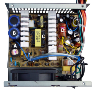
A switched-mode power supply (SMPS), also called switching-mode power supply, switch-mode power supply, switched power supply, or simply switcher, is an electronic power supply that incorporates a switching regulator to convert electrical power efficiently.

Balanced audio is a method of interconnecting audio equipment using balanced interfaces. This type of connection is very important in sound recording and production because it allows the use of long cables while reducing susceptibility to external noise caused by electromagnetic interference. The balanced interface guarantees that induced noise appears as common-mode voltages at the receiver which can be rejected by a differential device.

<span class="mw-page-title-main">Instrumentation amplifier</span> Electronic amplifier, a circuit component

An instrumentation amplifier is a type of differential amplifier that has been outfitted with input buffer amplifiers, which eliminate the need for input impedance matching and thus make the amplifier particularly suitable for use in measurement and test equipment. Additional characteristics include very low DC offset, low drift, low noise, very high open-loop gain, very high common-mode rejection ratio, and very high input impedances. Instrumentation amplifiers are used where great accuracy and stability of the circuit both short- and long-term are required.

<span class="mw-page-title-main">Differential amplifier</span> Electrical circuit component which amplifies the difference of two analog signals

A differential amplifier is a type of electronic amplifier that amplifies the difference between two input voltages but suppresses any voltage common to the two inputs. It is an analog circuit with two inputs and and one output , in which the output is ideally proportional to the difference between the two voltages:

<span class="mw-page-title-main">Opto-isolator</span> Insulates two circuits from one another while allowing signals to pass through in one direction

An opto-isolator is an electronic component that transfers electrical signals between two isolated circuits by using light. Opto-isolators prevent high voltages from affecting the system receiving the signal. Commercially available opto-isolators withstand input-to-output voltages up to 10 kV and voltage transients with speeds up to 25 kV/μs.

In an electrical system, a ground loop or earth loop occurs when two points of a circuit are intended to have the same ground reference potential but instead have a different potential between them. This is typically caused when enough current is flowing in the connection between the two ground points to produce a voltage drop and cause two points to be at different potentials. Current may be produced in a circular ground connection by electromagnetic induction.

Multiple electronic amplifiers can be connected such that they drive a single floating load (bridge) or a single common load (parallel), to increase the amount of power available in different situations. This is commonly encountered in audio applications.

This article illustrates some typical operational amplifier applications. A non-ideal operational amplifier's equivalent circuit has a finite input impedance, a non-zero output impedance, and a finite gain. A real op-amp has a number of non-ideal features as shown in the diagram, but here a simplified schematic notation is used, many details such as device selection and power supply connections are not shown. Operational amplifiers are optimised for use with negative feedback, and this article discusses only negative-feedback applications. When positive feedback is required, a comparator is usually more appropriate. See Comparator applications for further information.

<span class="mw-page-title-main">Charge amplifier</span>

A charge amplifier is an electronic current integrator that produces a voltage output proportional to the integrated value of the input current, or the total charge injected.

In electronics and signal processing, signal conditioning is the manipulation of an analog signal in such a way that it meets the requirements of the next stage for further processing.

<span class="mw-page-title-main">Test probe</span>

A test probe is a physical device used to connect electronic test equipment to a device under test (DUT). Test probes range from very simple, robust devices to complex probes that are sophisticated, expensive, and fragile. Specific types include test prods, oscilloscope probes and current probes. A test probe is often supplied as a test lead, which includes the probe, cable and terminating connector.

A fully differential amplifier (FDA) is a DC-coupled high-gain electronic voltage amplifier with differential inputs and differential outputs. In its ordinary usage, the output of the FDA is controlled by two feedback paths which, because of the amplifier's high gain, almost completely determine the output voltage for any given input.

<span class="mw-page-title-main">Transformer types</span> Overview of electrical transformer types

A variety of types of electrical transformer are made for different purposes. Despite their design differences, the various types employ the same basic principle as discovered in 1831 by Michael Faraday, and share several key functional parts.

In electrical engineering, a balanced circuit is electronic circuitry for use with a balanced line, or the balanced line itself. Balanced lines are a common method of transmitting many types of electrical signals between two points on two wires. In a balanced line, the two signal lines are of a matched impedance to help ensure that interference, induced in the line, is common-mode and can be removed at the receiving end by circuitry with good common-mode rejection. To maintain the balance, circuit blocks which interface to the line or are connected in the line must also be balanced.

In electrical engineering, a common-mode signal is the identical component of voltage present at both input terminals of an electrical device. In telecommunication, the common-mode signal on a transmission line is also known as longitudinal voltage.

<span class="mw-page-title-main">Oscilloscope</span> Instrument for displaying time-varying signals

An oscilloscope is a type of electronic test instrument that graphically displays varying voltages of one or more signals as a function of time. Their main purpose is capturing information on electrical signals for debugging, analysis, or characterization. The displayed waveform can then be analyzed for properties such as amplitude, frequency, rise time, time interval, distortion, and others. Originally, calculation of these values required manually measuring the waveform against the scales built into the screen of the instrument. Modern digital instruments may calculate and display these properties directly.

<span class="mw-page-title-main">Current sensing</span>

In electrical engineering, current sensing is any one of several techniques used to measure electric current. The measurement of current ranges from picoamps to tens of thousands of amperes. The selection of a current sensing method depends on requirements such as magnitude, accuracy, bandwidth, robustness, cost, isolation or size. The current value may be directly displayed by an instrument, or converted to digital form for use by a monitoring or control system.

References

  1. 1 2 3 Paul Horowitz, Winfield Hill The Art of Electronics Second Edition, Cambridge, 1989 ISBN   0-521-37095-7 pages 462-464