Key (engineering)

Last updated

In mechanical engineering, a key is a machine element used to connect a rotating machine element to a shaft. The key prevents relative rotation between the two parts and may enable torque transmission. For a key to function, the shaft and rotating machine element must have a keyway and a keyseat, which is a slot and pocket in which the key fits. The whole system is called a keyed joint. [1] [2] A keyed joint may allow relative axial movement between the parts.

Contents

Commonly keyed components include gears, pulleys, couplings, and washers.

Types

There are five main types of keys: sunk, saddle, tangent, round, and spline.

Sunk key

Types of sunk keys: rectangular, square, parallel sunk, gib-head, feather, and Woodruff.
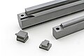
Parallel keys

Parallel keys are the most widely used. They have a square or rectangular cross-section. Square keys are used for smaller shafts and rectangular faced keys are used for shaft diameters over 6.5 in (170 mm) or when the wall thickness of the mating hub is an issue. Set screws often accompany parallel keys to lock the mating parts into place. [3] The keyway is a longitudinal slot in both the shaft and mating part.

W = d/4[ clarification needed ]
H = 2d/3[ clarification needed ]

where

  • W is the key width
  • H is the key height
  • d is the shaft diameter
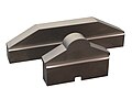
Woodruff keys

Woodruff keys are semicircular, fitting partly into a circular segment keyway with the remainder fitting into a longitudinal slot keyway in the mating part. The circular segment can be cut directly by plunge cutting with a circular Woodruff cutter without any reliefs. The main advantage of the Woodruff key is the elimination of milling near shaft shoulders, where stress concentrations, [4] and concentricity would be affected. [3] The latter is particularly important for high speed operation. The more exact fit of the key and keyway also reduces play, and stress concentrations in, and improves the reliability of the key. An additional advantage is a stuck key can be removed from a shaft with a hammer blow, the circular profile will push the key out of the slot, as opposed to a standard key which will need to be pushed axially, or pulled out of its slot. Common applications include machine tools, automotive applications, snowblowers and marine propellers.

This type of key was developed by William N. Woodruff of Hartford Connecticut. In 1888, he was awarded the John Scott Medal by the Franklin Institute for his invention. [5]

Tapered keys

The tapered key is tapered only on the side that engages the hub. The keyway in the hub has a taper that matches that of the tapered key. Some taper keys have a gib, or tab, for easy removal during disassembly. The purpose of the taper is to secure the key itself, as well as to firmly engage the shaft to the hub without the need for a set screw. The problem with taper keys is that they can cause the center of the shaft rotation to be slightly off of the mating part. [3] It is different from a tapered shaft lock in that tapered keys have a matching taper on the keyway, while tapered shaft locks do not.

Others

A Scotch key or Dutch key features a circular keyway hole (instead of rectangular), produced by drilling axially into the assembled hub and shaft, with a metal dowel pin serving as the key. If the hole and key are tapered, the key is referred to as a Dutch pin, which is driven in and optionally finished by cutting or grinding flush with the end of the shaft. If a straight Dutch keyway hole is optionally tapped with a thread, then an ordinary screw serves as the threaded Dutch key.

Spring pins are an alternative Dutch key component, instead of solid dowel pins. A spring pin is self-fastening and does not work loose under vibration. Hollow spring pins provide a weaker shear strength than a solid dowel pin, and the strength may be varied by varying the wall thickness. This limited shear strength specification is designed to sustain normal operation, but then give way in the event of excessive shaft torque, thus protecting the rest of the machine from damage.

Introducing an additional bushing component between hub and shaft improves the performance and convenience of keyed joints. Taper-Lock bushings are keyed hub fittings which provide three threaded Dutch keyways and two setscrews as Dutch keys, in addition to the rectangular keyway. The Dutch keyways are threaded only on the alternate hub side or shaft side, with a thread clearance hole form on the opposite side. By simply driving setscrews into selected holes, the hub mechanism conveniently operates to rigidly lock or definitely release from the shaft, without hammering or hub-pulling. Quick-disconnect (QD) bushings work similarly, but place a circular pattern of three unthreaded and three fully threaded holes further out from the shaft axis on a bushing flange, instead of across the bushing-to-hub interface.

A Hirth joint is similar to a spline joint but with the teeth on the end of the shaft instead of on the surface.

Saddle keys

These types of keys are generally attached to the driving member (e.g. shafts). These types of keys have less strength as compared with the sunk keys. These are rarely used keys, to transmit lower power to the driven members (e.g. couplings)
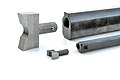
Tangent keys

Tangent keys are used in high-torque heavy-duty applications. What would have been the side of each keyway forms heels against which the key sits, and transfers force compressively. This latter point means that for reversible motion of the shaft, another key along a tangent outwards in the opposing direction is needed. Typically this will be offset by 90° or 180° on the shaft. The key may be wedge, rectangular, or square shaped, but particularly rectangular double-taper keys are used.

Spline key

This type of key uses multiple keyways in the hub to transmit high power.

Keyseating

Keyseating is the creation of the slots in the mating items. Keyseating can be done on a variety of different machines including a broach, a keyseater, wire-cut EDM, a shaper or vertical slotting machine, either a vertical or horizontal mill, or with a chisel and file.

Broaching

Broaching is primarily used to cut square cornered internal keyways. The specific broach, bushing and guide are used for each given keyway cross-section, which makes this process more expensive than most of the alternatives. However, it can produce the most accurate keyway out of all the processes. There are three main steps in broaching a keyway: First, the workpiece is set on the arbor press and the bushing is placed in the opening of the workpiece. Next, the broach is inserted and pushed through, cutting the keyway. Finally, shims are placed between the bushing and the broach to achieve the correct depth necessary for the key. [6]

Keyseater

A keyseater and a sample of various shapes that can be cut Keyseater and sample.png
A keyseater and a sample of various shapes that can be cut
Modern keyseating machine Maschine002.jpg
Modern keyseating machine

Keyseaters, also known as keyseating machines and keyway cutters, are specialized machines designed to cut keyways. They are very similar to vertical shapers; the difference is that the cutting tool on a keyseater enters the workpiece from the bottom and cuts on the down-stroke, while the tool on a shaper enters the workpiece from the top and cuts downward. Another difference is a keyseater has a guiding system above the workpiece to minimize deflection, which results in a closer tolerance cut. The process starts by clamping the workpiece to the table with a fixture or vise. The workpiece is properly located and then the reciprocating arm is started. Some models have a stationary table so the cutter is fed horizontally into the workpiece, while others have a movable table that feeds the workpiece into a fixed cutter. These machines can cut other straight sided features other than keyways (see the picture). They can also produce blind slots, which are slots that do not extend through the whole workpiece. [7] [8]

Wire-cut electrical-discharge machining (EDM)

Wire-cut electrical-discharge machining (EDM) is primarily used for small production lot sizes where either extreme precision is required or other cutting technologies are not readily available. Wire-cut EDM cuts keyways by eroding material away from the workpiece through a series of rapid electric current discharges between a spooling wire and the workpiece through a dielectric liquid. Computer numerical control (CNC) wire-cut EDM machines allow for a wide variety selection of keyways to be cut, inclusive of multiple keyways on the same hub. The main limitations of CNC wire-cut EDM is the time it takes to cut a keyway as well as the size of parts a given wire-cut EDM machine can accommodate. [9]

Shaping or slotting

Shaping or slotting is largely used for cutting keyways that do not extend through the full length of the part. Like keyseating, shaping uses a single-point cutting tool for cutting, however, shapers are not guided through the cut on a fixed post. As such, shaper cuts are generally more susceptible to deflection than keyseater cuts. [9]

Milling

Parallel, tapered, and Woodruff keyways can be produced on a milling machine. End mills or slotting cutters are used for parallel and tapered keyways, while a Woodruff cutter is used for Woodruff keyways. [10]

For internal keyways that are not too long, the keyways can be milled if a radius is acceptable.

Chiseling

One of the earliest forms of keyseating was done by chiseling. The keyway is roughed out using a chisel and then filed to size; the key is tried frequently to avoid over filing. This technique is long, tedious, and rarely used anymore. [11]

Keyed joints

A shear key is a feature intended to fail and avoid further damage should the machinery be accidentally operated in excess of its design limits. Shear keys may be any of the designs described above, but are made from a weaker material than the shaft. The shear key is easily and inexpensively replaced, and avoids more serious damage to the mechanism that would be costly or difficult to repair. For example, a steel shaft and pulley may employ a brass key. When excessive torque is applied to the joint, the steel edges shear the brass key into two pieces, leaving the pulley spinning loosely on the shaft and relieving the rest of the machine from possible damage.

Two parallel keys can be used if the shaft connection requires a higher torque rating. [3]

Improperly machined keyways that had cutter deflection or drifting occur, may not be strong enough for the required application. [12]

See also

Related Research Articles

<span class="mw-page-title-main">Coupling</span> Mechanical connection between two objects

A coupling is a device used to connect two shafts together at their ends for the purpose of transmitting power. The primary purpose of couplings is to join two pieces of rotating equipment while permitting some degree of misalignment or end movement or both. In a more general context, a coupling can also be a mechanical device that serves to connect the ends of adjacent parts or objects. Couplings do not normally allow disconnection of shafts during operation, however there are torque-limiting couplings which can slip or disconnect when some torque limit is exceeded. Selection, installation and maintenance of couplings can lead to reduced maintenance time and maintenance cost.

<span class="mw-page-title-main">Electrical discharge machining</span> Metal fabrication process

Electrical discharge machining (EDM), also known as spark machining, spark eroding, die sinking, wire burning or wire erosion, is a metal fabrication process whereby a desired shape is obtained by using electrical discharges (sparks). Material is removed from the work piece by a series of rapidly recurring current discharges between two electrodes, separated by a dielectric liquid and subject to an electric voltage. One of the electrodes is called the tool-electrode, or simply the tool or electrode, while the other is called the workpiece-electrode, or work piece. The process depends upon the tool and work piece not making physical contact.

<span class="mw-page-title-main">Lathe</span> Machine tool which rotates the work piece on its axis

A lathe is a machine tool that rotates a workpiece about an axis of rotation to perform various operations such as cutting, sanding, knurling, drilling, deformation, facing, and turning, with tools that are applied to the workpiece to create an object with symmetry about that axis.

<span class="mw-page-title-main">Shaper</span> Machine tool which linearly cuts or grinds the workpiece

In machining, a shaper is a type of machine tool that uses linear relative motion between the workpiece and a single-point cutting tool to machine a linear toolpath. Its cut is analogous to that of a lathe, except that it is (archetypally) linear instead of helical.

<span class="mw-page-title-main">Metalworking</span> Process of making items from metal

Metalworking is the process of shaping and reshaping metals to create useful objects, parts, assemblies, and large scale structures. As a term it covers a wide and diverse range of processes, skills, and tools for producing objects on every scale: from huge ships, buildings, and bridges down to precise engine parts and delicate jewelry.

<span class="mw-page-title-main">Hobbing</span> Process used to cut teeth into gears

Hobbing is a machining process for gear cutting, cutting splines, and cutting sprockets on a hobbing machine, which is a special type of milling machine. The teeth or splines of the gear are progressively cut into the material by a series of cuts made by a cutting tool called a hob.

<span class="mw-page-title-main">File (tool)</span> Tool used to remove fine amounts of material

A file is a tool used to remove fine amounts of material from a workpiece. It is common in woodworking, metalworking, and other similar trade and hobby tasks. Most are hand tools, made of a case hardened steel bar of rectangular, square, triangular, or round cross-section, with one or more surfaces cut with sharp, generally parallel teeth. A narrow, pointed tang is common at one end, to which a handle may be fitted.

Broaching is a machining process that uses a toothed tool, called a broach, to remove material. There are two main types of broaching: linear and rotary. In linear broaching, which is the more common process, the broach is run linearly against a surface of the workpiece to produce the cut. Linear broaches are used in a broaching machine, which is also sometimes shortened to broach. In rotary broaching, the broach is rotated and pressed into the workpiece to cut an axisymmetric shape. A rotary broach is used in a lathe or screw machine. In both processes the cut is performed in one pass of the broach, which makes it very efficient.

<span class="mw-page-title-main">Grinding machine</span> Machine tool used for grinding

A grinding machine, often shortened to grinder, is a power tool used for grinding. It is a type of machining using an abrasive wheel as the cutting tool. Each grain of abrasive on the wheel's surface cuts a small chip from the workpiece via shear deformation.

<span class="mw-page-title-main">Collet</span> Type of chuck

A collet is a segmented sleeve, band or collar. One of the two radial surfaces of a collet is usually tapered and the other is cylindrical. The term collet commonly refers to a type of chuck that uses collets to hold either a workpiece or a tool but has other mechanical applications.

<span class="mw-page-title-main">Machine taper</span>

A machine taper is a system for securing cutting tools or toolholders in the spindle of a machine tool or power tool. A male member of conical form fits into the female socket, which has a matching taper of equal angle.

<span class="mw-page-title-main">Turning</span> Machining process

Turning is a machining process in which a cutting tool, typically a non-rotary tool bit, describes a helix toolpath by moving more or less linearly while the workpiece rotates.

The shank is the end of a drill bit grasped by the chuck of a drill. The cutting edges of the drill bit contact the workpiece, and are connected via the shaft with the shank, which fits into the chuck. In many cases a general-purpose arrangement is used, such as a bit with cylindrical shaft and shank in a three-jaw chuck which grips a cylindrical shank tightly. Different shank and chuck combination can deliver improved performance, such as allowing higher torque, greater centering accuracy, or moving the bit independently of the chuck, with a hammer action.

Milling cutters are cutting tools typically used in milling machines or machining centres to perform milling operations. They remove material by their movement within the machine or directly from the cutter's shape.

<span class="mw-page-title-main">Metal lathe</span> Machine tool used to remove material from a rotating workpiece

In machining, a metal lathe or metalworking lathe is a large class of lathes designed for precisely machining relatively hard materials. They were originally designed to machine metals; however, with the advent of plastics and other materials, and with their inherent versatility, they are used in a wide range of applications, and a broad range of materials. In machining jargon, where the larger context is already understood, they are usually simply called lathes, or else referred to by more-specific subtype names. These rigid machine tools remove material from a rotating workpiece via the movements of various cutting tools, such as tool bits and drill bits.

In the context of machining, a cutting tool or cutter is typically a hardened metal tool that is used to cut, shape, and remove material from a workpiece by means of machining tools as well as abrasive tools by way of shear deformation. The majority of these tools are designed exclusively for metals.

<span class="mw-page-title-main">Planer (metalworking)</span> Machining tool which uses linear relative motion between the workpiece and tool bit

A planer is a type of metalworking machine tool that uses linear relative motion between the workpiece and a single-point cutting tool to cut the work piece. A planer is similar to a shaper, but larger, and with workpiece moving, whereas in a shaper the cutting tool moves.

Splines are ridges or teeth on a drive shaft that matches with grooves in a mating piece and transfer torque to it, maintaining the angular correspondence between them.

<span class="mw-page-title-main">Screw</span> Type of fastener characterized by a thread wrapped around a cylinder core

A screw and a bolt are similar types of fastener typically made of metal and characterized by a helical ridge, called a male thread. Screws and bolts are used to fasten materials by the engagement of the screw thread with a similar female thread in a matching part.

In manufacturing, threading is the process of creating a screw thread. More screw threads are produced each year than any other machine element. There are many methods of generating threads, including subtractive methods ; deformative or transformative methods ; additive methods ; or combinations thereof.

References

  1. Bhandari, V. B. (2007), Design of machine elements (2nd ed.), Tata McGraw-Hill, p. 340, ISBN   978-0-07-061141-2.
  2. Leonard 1919 , p. 394.
  3. 1 2 3 4 Keys and Keyways (PDF), archived from the original (PDF) on 2011-06-14, retrieved 2010-03-19.
  4. Shigley, Joseph; Mischke, Charles (1989), Mechanical Engineering Design (5 ed.), McGraw-Hill, ISBN   0-07-331657-1.
  5. Garfield, Eugene (2007). "The John Scott Award Recipients from 1826 - present" . Retrieved 2007-08-23.
  6. Krar, S. F. (1983). Machine tool operations. (pp. 84–85). New York: Gregg Division McGraw-Hill.
  7. Keyseating , retrieved 2010-01-30.
  8. Wick, C. H. (1964). Versatility of keyseating. Machinery (NY), 70(8), 138-140.
  9. 1 2 Cutting Keyways - Broaching, Keyseating, Wire-Cut EDM, Shaping, & Milling , retrieved 2014-12-03.
  10. Kibbe, R. R. (1995). Machine tool practices. (5th ed. ed., p. 572). Englewood Cliffs, New Jersey: Prentice-Hall, Inc.
  11. Leonard 1919 , p. 40.
  12. Romig, J. V. (1926). The Popular Science Monthly. The Popular Science Monthly., 110(5), 72, 124.

Bibliography