In electronics, the figures of merit of an amplifier are numerical measures that characterize its properties and performance. Figures of merit can be given as a list of specifications that include properties such as gain, bandwidth, noise and linearity, among others listed in this article. Figures of merit are important for determining the suitability of a particular amplifier for an intended use.

An amplifier, electronic amplifier or (informally) amp is an electronic device that can increase the magnitude of a signal. It is a two-port electronic circuit that uses electric power from a power supply to increase the amplitude of a signal applied to its input terminals, producing a proportionally greater amplitude signal at its output. The amount of amplification provided by an amplifier is measured by its gain: the ratio of output voltage, current, or power to input. An amplifier is defined as a circuit that has a power gain greater than one.
In signal processing, distortion is the alteration of the original shape of a signal. In communications and electronics it means the alteration of the waveform of an information-bearing signal, such as an audio signal representing sound or a video signal representing images, in an electronic device or communication channel.

Electromagnetic compatibility (EMC) is the ability of electrical equipment and systems to function acceptably in their electromagnetic environment, by limiting the unintentional generation, propagation and reception of electromagnetic energy which may cause unwanted effects such as electromagnetic interference (EMI) or even physical damage to operational equipment. The goal of EMC is the correct operation of different equipment in a common electromagnetic environment. It is also the name given to the associated branch of electrical engineering.
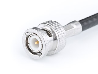
The BNC connector is a miniature quick connect/disconnect radio frequency connector used for coaxial cable. It is designed to maintain the same characteristic impedance of the cable, with 50 ohm and 75 ohm types being made. It is usually applied for video and radio frequency connections up to about 2 GHz and up to 500 volts. The connector has a twist to lock design with two lugs in the female portion of the connector engaging a slot in the shell of the male portion. The type was introduced on military radio equipment in the 1940s and has since become widely applied in radio systems, and is a common type of video connector. Similar radio-frequency connectors differ in dimensions and attachment features, and may allow for higher voltages, higher frequencies, or three-wire connections.

An anechoic chamber is a room designed to stop reflections or echoes of either sound or electromagnetic waves. They are also often isolated from energy entering from their surroundings. This combination means that a person or detector exclusively hears direct sounds, in effect simulating being outside in a free field.

Audio system measurements are a means of quantifying system performance. These measurements are made for several purposes. Designers take measurements so that they can specify the performance of a piece of equipment. Maintenance engineers make them to ensure equipment is still working to specification, or to ensure that the cumulative defects of an audio path are within limits considered acceptable. Audio system measurements often accommodate psychoacoustic principles to measure the system in a way that relates to human hearing.

A spectrum analyzer measures the magnitude of an input signal versus frequency within the full frequency range of the instrument. The primary use is to measure the power of the spectrum of known and unknown signals. The input signal that most common spectrum analyzers measure is electrical; however, spectral compositions of other signals, such as acoustic pressure waves and optical light waves, can be considered through the use of an appropriate transducer. Spectrum analyzers for other types of signals also exist, such as optical spectrum analyzers which use direct optical techniques such as a monochromator to make measurements.

In electronics, electrical termination is the practice of ending a transmission line with a device that matches the characteristic impedance of the line. Termination prevents signals from reflecting off the end of the transmission line. Reflections at the ends of unterminated transmission lines cause distortion, which can produce ambiguous digital signal levels and misoperation of digital systems. Reflections in analog signal systems cause such effects as video ghosting, or power loss in radio transmitter transmission lines.

Electromagnetic interference (EMI), also called radio-frequency interference (RFI) when in the radio frequency spectrum, is a disturbance generated by an external source that affects an electrical circuit by electromagnetic induction, electrostatic coupling, or conduction. The disturbance may degrade the performance of the circuit or even stop it from functioning. In the case of a data path, these effects can range from an increase in error rate to a total loss of the data. Both human-made and natural sources generate changing electrical currents and voltages that can cause EMI: ignition systems, cellular network of mobile phones, lightning, solar flares, and auroras. EMI frequently affects AM radios. It can also affect mobile phones, FM radios, and televisions, as well as observations for radio astronomy and atmospheric science.

A Q meter is a piece of equipment used in the testing of radio frequency circuits. It has been largely replaced in professional laboratories by other types of impedance measuring devices, though it is still in use among radio amateurs. It was developed at Boonton Radio Corporation in Boonton, New Jersey in 1934 by William D. Loughlin.
A comb generator is a signal generator that produces multiple harmonics of its input signal. The appearance of the output at the spectrum analyzer screen, resembling teeth of a comb, gave the device its name.

In electronics, a choke is an inductor used to block higher-frequency alternating currents (AC) while passing direct current (DC) and lower-frequency ACs in a circuit. A choke usually consists of a coil of insulated wire often wound on a magnetic core, although some consist of a doughnut-shaped ferrite bead strung on a wire. The choke's impedance increases with frequency. Its low electrical resistance passes both AC and DC with little power loss, but its reactance limits the amount of AC passed.
A quasi-peak detector is a type of electronic detector or rectifier. Quasi-peak detectors for specific purposes have usually been standardized with mathematically precisely defined dynamic characteristics of attack time, integration time, and decay time or fall-back time.
In telecommunication, a measuring receiver or measurement receiver is a calibrated laboratory-grade radio receiver designed to measure the characteristics of radio signals. The parameters of such receivers can usually be adjusted over a much wider range of values than is the case with other radio receivers. Their circuitry is optimized for stability and to enable calibration and reproducible results. Some measurement receivers also have especially robust input circuits that can survive brief impulses of more than 1000 V, as they can occur during measurements of radio signals on power lines and other conductors.
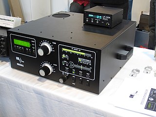
A valve RF amplifier or tube amplifier (U.S.) is a device for electrically amplifying the power of an electrical radio frequency signal.
In the field of EMC, active EMI reduction refers to techniques aimed to reduce or to filter electromagnetic noise (EMI) making use of active electronic components. Active EMI reduction contrasts with passive filtering techniques, such as RC filters, LC filters RLC filters, which includes only passive electrical components. Hybrid solutions including both active and passive elements exist. Standards concerning conducted and radiated emissions published by IEC and FCC set the maximum noise level allowed for different classes of electrical devices. The frequency range of interest spans from 150 kHz to 30 MHz for conducted emissions and from 30 MHz to 40 GHz for radiated emissions. Meeting these requirements and guaranteeing the functionality of an electrical apparatus subject to electromagnetic interference are the main reason to include an EMI filter. In an electrical system, power converters, i.e. DC/DC converters, inverters and rectifiers, are the major sources of conducted EMI, due to their high-frequency switching ratio which gives rise to unwanted fast current and voltage transients. Since power electronics is nowadays spread in many fields, from power industrial application to automotive industry, EMI filtering has become necessary. In other fields, such as the telecommunication industry where the major focus is on radiated emissions, other techniques have been developed for EMI reduction, such as spread spectrum clocking which makes use of digital electronics, or electromagnetic shielding.
The MIL-STD-883 standard establishes uniform methods, controls, and procedures for testing microelectronic devices suitable for use within military and aerospace electronic systems including basic environmental tests to determine resistance to deleterious effects of natural elements and conditions surrounding military and space operations; mechanical and electrical tests; workmanship and training procedures; and such other controls and constraints as have been deemed necessary to ensure a uniform level of quality and reliability suitable to the intended applications of those devices. For this standard, the term "devices" includes monolithic, multichip, film and hybrid microcircuits, microcircuit arrays, and the elements from which the circuits and arrays are formed. This standard is intended to apply only to microelectronic devices.
MIL-STD-461 is a United States Military Standard that describes how to test equipment for electromagnetic compatibility.

