As interoperability between platforms was difficult, there was little purpose to, or effort expended on, using standardized formats. The main exception to this rule was the Kansas City standard, which was supported by most S-100 bus based computers and was later adopted by a few other vendors like the BBC Computer and MSX. It also saw use as an exchange medium in some magazines and even broadcast over the radio in Europe.
RCA COSMAC
One of the earliest efforts to develop a microcomputer for home use was carried out in the early 1970s at RCA and led to the COSMAC processor design. As part of this process, a cassette interface was developed. This used a frequency-shift keying (FSK) system, with binary zeros ("space") represented by one cycle of a 2kHz signal, and ones ("mark") as a cycle of 0.8kHz. Bytes were written with a single mark bit, eight data bits, and a final odd parity bit. Files were prefixed with four seconds of space signals to provide clock recovery, and then all of the data written in a single stream. There was no support for reading and writing the data in the basic operating system; users had to type in their own loader program to do so, although the hexadecimal example version of the code was provided and is quite small.[1]
HITS
The Hobbyist Interchange Tape System (HITS) was introduced by Jerry Ogdin in a September 1975 article in Popular Electronics magazine. In contrast to almost every other system of the era, HITS did not use FSK for its storage mechanism; instead it used pulse-width modulation, or PWM. Any suitable carrier frequency could be used, with 2000Hz being suggested. The article goes on to note that the basic concept works well at any frequency and that the system is capable of recording at data at a rate of about 1⁄4 of the carrier. This means that a 10kHz carrier allows about 2,500bit/s speeds.[2]
Zeros were recorded as short pulses, and ones long, with the overall bit time being a nominal 2.5milliseconds when used at 2kHz. The pulse lengths were measured by recording the time between the off-to-on transition when the carrier turned on and the on-to-off transition when it dropped again. This was compared to the time between the on-to-off and the next off-to-on marking the start of the next bit. If the on portion of the pulse was shorter than the off period, it was a 0; if the on portion was longer than off, it was 1. This meant every bit in the recording was self-timed, allowing it to easily survive tape stretch and other problems that changed the frequency or playback speed.[2]
The Kansas City Standard (KCS) was one of the few cassette formats that was standardized to any degree. It was created by a group of S-100 bus manufacturers at a meeting hosted by Byte Magazine in November 1975 in Kansas City.[3]
KCS was a simple FSK system that recorded zeros as four cycles of a 1200Hz tone and ones as eight cycles of 2400Hz. This produces an overall data rate of 300Hz. Data was recorded in eight-bit bytes, least significant bit first, with a parity bit added to seven-bit data if needed. A single space was added to the front and a single mark to the end to act as start and stop bits. The bytes were written individually, with the tone returning to the mark frequency between characters. If shorter data was being written, for instance, six-bit ASCII codes, any unused bits were filled with mark at the end to fill out eight bits. The data was written using a slightly modified version of Manchester encoding.[3]
No file format was specified beyond adding five seconds of marks at the start of the file, nor was any example code provided. This would be up to the vendors of the plug-in cards to provide.[3]
KCS variations
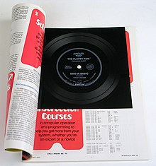
Interface Age magazine May 1977 issue, with a Kansas City Standard flexi disc floppy ROM
CUTS was a faster version of the KCS system, developed by Processor Technology. It used a single cycle of 1200Hz for a space and two cycles of 2400Hz for a mark. This made the effective data rate 1200bit/s, four times that of the KCS version. The CUTS S-100 board could support either CUTS or KCS for reading and writing and could support two tape decks from a single board.[4]Acorn Computers Ltd implemented both the original 300-baud KCS and the 1200-baud CUTS variation in their BBC Micro and Acorn Electron.[5][lower-alpha 1]
MSX took this another step to 2400bit/s by moving to higher frequencies, using a single 2400Hz cycle for a space and two cycles of 4800Hz for a mark.[6] Additionally, MSX defined a block-based file format, although it changed several times. Blocks could contain between 0 and 255 bytes of data with header information and a one-byte checksum, later changing to a 16-bit cyclic redundancy check (CRC).[7]
Other formats
After introducing CUTS, Bob Marsh approached Bob Jones, the publisher of Interface Age magazine, about the possibility of binding Flexi disc recordings into the magazine as a distribution mechanism. Their first attempt did not work and they moved on to other projects. The concept was then picked up by Daniel Meyer and Gary Kay of Southwest Technical Products (SWTPC), who arranged for Robert Uiterwyk to provide his 4K BASIC interpreter program for the Motorola 6800 in KCS format. Several attempts were required before they came up with a workable process of producing the discs. The May 1977 issue of Interface Age contains the first "Floppy ROM", a 331⁄3 RPM record containing about six minutes of Kansas City standard audio.[8] Several additional such discs were distributed.
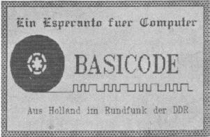
The 1200-baud CUTS variation was also used as the basis for the BASICODE system, which broadcast BASIC programs over commercial radio.[9] In this case, a five-second header and footer of the 2400Hz signal was added to the file, and the program was sent as a single long series of ASCII bytes. The bytes were sent with a single mark start bit, eight bits of data containing a seven-bit ASCII code with the most significant bit set to 1, and a single mark stop bit. Users would record the programs to tape using their stereo equipment and then read the tapes in their existing computer decks.[10]
Apple
Prior to the introduction of the Disk II, cassette was the main storage medium for Apple machines. Here an Apple II is using a Panasonic tape deck.
The Apple I introduced an expansion-card based cassette system similar to KCS, recording a single cycle of 2000Hz for a space and a single cycle of 1000Hz for a mark. This resulted in an average speed of about 1500bit/s. The associated device driver in PROM offered an interactive mode that allowed users to write memory locations to tape. For instance, typing E000.EFFFR would read (the R at the end) data from the tape into memory locations $E000 to $EFFF (4kB of data). When writing, 10 seconds of the mark signal was added as a header before it began to write the requested data.[11]
The Apple II moved the cassette interface onto the motherboard and made several changes to the format. The mark and space signals remained the same as in the original version, but the header was now ten seconds at 770Hz followed by a new "sync tone" of one half cycle of 2500Hz and one half cycle of 2000Hz. Data following the header was recoded as before, but was also appended with an 8-bit checksum. Applesoft BASIC saved user programs as two "records", the first consisting of the header signal followed by the program length and checksum and the second with the header signal, program data and checksum.[12]
TI-99/4
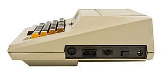
TI Program Recorder
The format for the TI-99/4 was driven by internal I/O pins being toggled at the rate needed to produce the proper tones on the cassette. This was accomplished by the TMS9901 support chip, which offered various clock dividers. For cassette operations, the clock divider was set to 17, and the input to the chip was the system's main 3MHz clock divided by 64. Thus the output of the TMS9901 was 17 / (3MHz / 64) = 363.6 microseconds, or 2750Hz. To write a one to tape, the signal was toggled with every clock output, whereas a zero skipped one cycle. The result was that a mark was two cycles of 1379Hz while spaces were a single cycle of 690Hz. The resulting data rate was about 700bit/s.[13]
The system also included a simple file format consisting of a 768-byte lead-in followed by a header with the number of blocks in the file. The data was encoded in blocks; these started with 8-byte lead-in of spaces and a single mark, then 64 bytes of data, and finally a 1-byte checksum, for a total length of 73 bytes. Every block was repeated twice as an error correction system, thus halving the effective data rate.[13]
The lead-in at the start of the file produced a steady tone that was used to measure the actual data rate on the tape, which might change due to tape stretch or differences between machines. During a read, the system set an input timer to the maximum value of $3FFF and then read one byte. When the byte was complete the timer was examined to see how many cycles had passed. This might be 16 or 18, for instance. This value was then put into the clock timer. During reads, if the signal did not cycle during a clock cycle it was a 0; if it did it was a space.[13]
The Commodore tape format, introduced on the Commodore PET, uses a combination of FSK and PWM methodology. Bits were encoded within a fixed time period similar to PWM, but because the I/O hardware on most Commodore models responded only to the falling edge of a cycle, they were not capable of true PWM decoding. Instead, the fixed time period contained two complete cycles of differing lengths to simulate a PWM pulse and 'off' period. Zeros were encoded by a "short" cycle[lower-alpha 2] followed by a "medium" cycle, while ones were encoded as a medium cycle then short cycle. The signals were sent directly from the output pin as a square wave which was "rounded off" by the recording media. A third "long" cycle was used for special tones: long-medium marked the start of each byte, long-short marked the end of data.[14][15]
The primary use of the system was with Commodore BASIC, which recorded a header containing a series of bytes used as a way for the system to track the tape speed, followed by the file name, size and other data. The header was then repeated as a way to deal with data corruption. The program data followed as a single long stream of bytes, and was itself written a second time for the same reason.[14]
It was possible to bypass the Commodore tape format routines and access the I/O hardware directly, which allowed for the widespread development of 'turbo' loaders for Commodore computers.[14]
The Atari 8-bit computers use a system based on consultations with recording engineers, one of the most obvious outcomes being to use two frequencies that were not harmonics of each other. Ones are represented by 5327Hz, and zeros by 3995Hz, toggling at 600Hz.[16]
The operating system defines a packet-oriented file format with 128 bytes of payload with two header bytes, a control byte, and a following checksum, making the packet a total of 132 bytes long. The two header bytes are character 55 hex, binary 01010101 01010101, which are used by the circuitry to perform clock recovery. The control byte has three values: $FC is a full-length packet, $FA a short packet with the length stored prior to the checksum, and finally $FE is the end-of-file (EOF) marker. Short packets and EOFs still contain a full 128-byte payload; they simply ignore the unused portions.[16]
Packets are separated by short periods of pure 5327Hz, a pre-record write tone and a post-record gap, which added together made the "inter-record gap" or IRG. When opened for writing, the driver can be set to one of two modes, with short or long IRGs. For binary formats, where the data is being copied directly to or from memory with no interpretation, the short IRG is used, about 0.25seconds. For other uses, like a BASIC programming language program in text format that has to be converted line by line to the internal binary format, the normal IRG is used, 3seconds. This time was chosen to allow the cassette deck to come to a complete stop and restart before reaching the next packet, allowing the system any amount of time needed to process the packet.[16]
Although there is a standard packet format, there is no defined file format used by the system as a whole. The closest thing is a header in bootable cassettes, which contains only 6 bytes of data and lacks a file name or other identifying information. The boot packet contains the number of records (up to 255) in the second byte, the low and high bytes of the address to load to, and the low and high address of the location to jump to once the load had completed.[16]
In addition to the standard packet format, the driver gives the user direct control over the tape drive motors and reading and writing the tones. This is used with audio tapes to control playback. A typical scenario has an audio recording on the "left" track and short bursts of 5327Hz at key locations within the audio. The program then starts the tape motor, causing the audio to be routed through the television speaker, waiting for a 1 to appear on the I/O port. When this is seen, the program stops the tape and waits for some user action before starting it again.[16]
Notes
↑ The BBC hardware definition incorrectly refers to the 300-baud speed as CUTS mode.
↑ The cycle frequencies for the Commodore 64 are 2840Hz for 'short' cycles, 1953Hz for 'medium' and 1488Hz for 'long', these vary on other Commodore models.
Related Research Articles
The Transmission Control Protocol (TCP) is one of the main protocols of the Internet protocol suite. It originated in the initial network implementation in which it complemented the Internet Protocol (IP). Therefore, the entire suite is commonly referred to as TCP/IP. TCP provides reliable, ordered, and error-checked delivery of a stream of octets (bytes) between applications running on hosts communicating via an IP network. Major internet applications such as the World Wide Web, email, remote administration, and file transfer rely on TCP, which is part of the Transport layer of the TCP/IP suite. SSL/TLS often runs on top of TCP.
Network throughput refers to the rate of message delivery over a communication channel, such as Ethernet or packet radio, in a communication network. The data that these messages contain may be delivered over physical or logical links, or through network nodes. Throughput is usually measured in bits per second, and sometimes in data packets per second or data packets per time slot.
In computer networking, the User Datagram Protocol (UDP) is one of the core communication protocols of the Internet protocol suite used to send messages to other hosts on an Internet Protocol (IP) network. Within an IP network, UDP does not require prior communication to set up communication channels or data paths.
In telecommunications and computer networking, a network packet is a formatted unit of data carried by a packet-switched network. A packet consists of control information and user data; the latter is also known as the payload. Control information provides data for delivering the payload. Typically, control information is found in packet headers and trailers.
The KIM-1, short for Keyboard Input Monitor, is a small 6502-based single-board computer developed and produced by MOS Technology, Inc. and launched in 1976. It was very successful in that period, due to its low price and easy-access expandability.
The Kansas City standard (KCS), or Byte standard, is a data storage protocol for standard cassette tapes at 300 bits per second. It originated in a symposium sponsored by Byte magazine in November 1975 in Kansas City, Missouri to develop a standard for the storage of digital microcomputer data on inexpensive consumer quality cassettes. The first systems based on the standard appeared in 1976.
Specific Area Message Encoding (SAME) is a protocol used for framing and classification of broadcasting emergency warning messages. It was developed by the United States National Weather Service for use on its NOAA Weather Radio (NWR) network, and was later adopted by the Federal Communications Commission for the Emergency Alert System, then subsequently by Environment Canada for use on its Weatheradio Canada service. It is also used to set off receivers in Mexico City and surrounding areas as part of the Mexican Seismic Alert System (SASMEX).
Modified frequency modulation (MFM) is a run-length limited (RLL) line code used to encode data on most floppy disks and some hard disk drives. It was first introduced on hard disks in 1970 with the IBM 3330 and then in floppy disk drives beginning with the IBM 53FD in 1976.
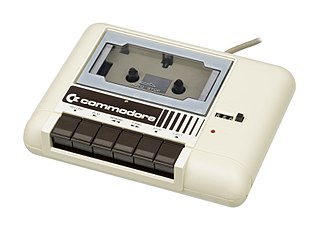
The Commodore 1530 (C2N) Datasette, later also Datassette, is Commodore's dedicated magnetic-tape data storage device. Using compact cassettes as the storage medium, it provides inexpensive storage to Commodore's 8-bit computers, including the PET, VIC-20, and Commodore 64. A physically similar model, Commodore 1531, was made for the Commodore 16 and Plus/4 series computers.
XMODEM is a simple file transfer protocol developed as a quick hack by Ward Christensen for use in his 1977 MODEM.ASM terminal program. It allowed users to transmit files between their computers when both sides used MODEM. Keith Petersen made a minor update to always turn on "quiet mode", and called the result XMODEM.
YMODEM is a file transfer protocol used between microcomputers connected together using modems. It was primarily used to transfer files to and from bulletin board systems. YMODEM was developed by Chuck Forsberg as an expansion of XMODEM and was first implemented in his CP/M YAM program. Initially also known as YAM, it was formally given the name "YMODEM" in 1985 by Ward Christensen, author of the original XMODEM.
The KC 85 were models of microcomputers built in East Germany by VEB Mikroelektronik "Wilhelm Pieck" Mühlhausen. The first model in the series, the HC 900, originally designed as a home computer and introduced in 1984, was renamed to KC 85/2 in 1985 to de-emphasize its use as consumer good.
MPEG transport stream or simply transport stream (TS) is a standard digital container format for transmission and storage of audio, video, and Program and System Information Protocol (PSIP) data. It is used in broadcast systems such as DVB, ATSC and IPTV.
Unified Emulator Format (UEF) is a container format for the compressed storage of audio tapes, ROMs, floppy discs and machine state snapshots for the 8-bit range of computers manufactured by Acorn Computers. First implemented by Thomas Harte's ElectrEm emulator and related tools, it is now supported by major emulators of Acorn machines and carried by two online archives of Acorn software numbering thousands of titles.
Intel hexadecimal object file format, Intel hex format or Intellec Hex is a file format that conveys binary information in ASCII text form, making it possible to store on non-binary media such as paper tape, punch cards, etc., to display on text terminals or be printed on line-oriented printers. The format is commonly used for programming microcontrollers, EPROMs, and other types of programmable logic devices and hardware emulators. In a typical application, a compiler or assembler converts a program's source code to machine code and outputs it into a object or executable file in hexadecimal format. In some applications, the Intel hex format is also used as a container format holding packets of stream data. Common file extensions used for the resulting files are .HEX or .H86. The HEX file is then read by a programmer to write the machine code into a PROM or is transferred to the target system for loading and execution. There are various tools to convert files between hexadecimal and binary format, and vice versa.
Protocol spoofing is used in data communications to improve performance in situations where an existing protocol is inadequate, for example due to long delays or high error rates.
BASICODE was a computer project intended to create a unified standard for the BASIC programming language. BASIC was available on many popular home computers, but there were countless variants that were mostly incompatible with each other. The project was initiated in 1980 by Hobbyscoop, a radio program of the Dutch broadcasting organisation Nederlandse Omroep Stichting (NOS).
The ZX Spectrum's software library was very diverse. While the majority of the software produced for the system was video games, others included programming language implementations, Sinclair BASIC extensions, databases, word processors, spread sheets, drawing and painting tools, and 3D modelling tools.
The Serial Input/Output system, universally known as SIO, was a proprietary peripheral bus and related software protocol stacks used on the Atari 8-bit computers to provide most input/output duties for those computers. Unlike most I/O systems of the era, such as RS-232, SIO included a lightweight protocol that allowed multiple devices to be attached to a single daisy-chained port that supported dozens of devices. It also supported plug-and-play operations. SIO's designer, Joe Decuir, credits his work on the system as the basis of USB.
The Atari Program Recorder is Atari's dedicated magnetic-tape data storage device for the Atari 8-bit computers. The original 410 was launched along with the Atari 400 and 800 machines in 1979. The 1010 was a smaller model introduced to match the styling of the XL series released in 1983. XC12 of 1986 matched the XE series and was sold mostly in eastern Europe and South America. Slight variations of all of these models were also introduced from time to time.
Cassetternet – Radiolab Mixtape episode on broadcasting programs over the radio
This page is based on this Wikipedia article Text is available under the CC BY-SA 4.0 license; additional terms may apply. Images, videos and audio are available under their respective licenses.