
A magnet is a material or object that produces a magnetic field. This magnetic field is invisible but is responsible for the most notable property of a magnet: a force that pulls on other ferromagnetic materials, such as iron, steel, nickel, cobalt, etc. and attracts or repels other magnets.

A magnetometer is a device that measures magnetic field or magnetic dipole moment. Different types of magnetometers measure the direction, strength, or relative change of a magnetic field at a particular location. A compass is one such device, one that measures the direction of an ambient magnetic field, in this case, the Earth's magnetic field. Other magnetometers measure the magnetic dipole moment of a magnetic material such as a ferromagnet, for example by recording the effect of this magnetic dipole on the induced current in a coil.

An electromagnet is a type of magnet in which the magnetic field is produced by an electric current. Electromagnets usually consist of wire wound into a coil. A current through the wire creates a magnetic field which is concentrated in the hole in the center of the coil. The magnetic field disappears when the current is turned off. The wire turns are often wound around a magnetic core made from a ferromagnetic or ferrimagnetic material such as iron; the magnetic core concentrates the magnetic flux and makes a more powerful magnet.
Magnetostriction is a property of magnetic materials that causes them to change their shape or dimensions during the process of magnetization. The variation of materials' magnetization due to the applied magnetic field changes the magnetostrictive strain until reaching its saturation value, λ. The effect was first identified in 1842 by James Joule when observing a sample of iron.
An actuator is a component of a machine that produces force, torque, or displacement, when an electrical, pneumatic or hydraulic input is supplied to it in a system. The effect is usually produced in a controlled way. An actuator translates such an input signal into the required form of mechanical energy. It is a type of transducer. In simple terms, it is a "mover".
A neodymium magnet (also known as NdFeB, NIB or Neo magnet) is a permanent magnet made from an alloy of neodymium, iron, and boron to form the Nd2Fe14B tetragonal crystalline structure. They are the most widely used type of rare-earth magnet.

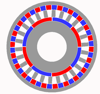
A Halbach array is a special arrangement of permanent magnets that augments the magnetic field on one side of the array while cancelling the field to near zero on the other side. This is achieved by having a spatially rotating pattern of magnetisation.
A magnetic shape-memory alloy (MSMA) is a type of smart material that can undergo significant and reversible changes in shape in response to a magnetic field. This behavior arises due to a combination of magnetic and shape-memory properties within the alloy, allowing it to produce mechanical motion or force under magnetic actuation. MSMAs are commonly made from ferromagnetic materials, particularly nickel-manganese-gallium (Ni-Mn-Ga), and are useful in applications requiring rapid, controllable, and repeatable movement.
Terfenol-D, an alloy of the formula TbxDy1−xFe2 (x ≈ 0.3), is a magnetostrictive material. It was initially developed in the 1970s by the Naval Ordnance Laboratory in the United States. The technology for manufacturing the material efficiently was developed in the 1980s at Ames Laboratory under a U.S. Navy-funded program. It is named after terbium, iron (Fe), Naval Ordnance Laboratory (NOL), and the D comes from dysprosium.
A samarium–cobalt (SmCo) magnet, a type of rare-earth magnet, is a strong permanent magnet made of two basic elements: samarium and cobalt.

A MEMS electrothermal actuator is a microelectromechanical device that typically generates motion by thermal expansion. It relies on the equilibrium between the thermal energy produced by an applied electric current and the heat dissipated into the environment or the substrate. Its working principle is based on resistive heating. Fabrication processes for electrothermal actuators include deep X-ray lithography, LIGA, and deep reactive ion etching (DRIE). These techniques allow for the creation of devices with high aspect ratios. Additionally, these actuators are relatively easy to fabricate and are compatible with standard Integrated Circuits (IC) and MEMS fabrication methods. These electrothermal actuators can be utilized in different kind of MEMS devices like microgrippers, micromirrors, tunable inductors and resonators.
Flux pumping is a method for magnetising superconductors to fields in excess of 15 teslas. The method can be applied to any type II superconductor and exploits a fundamental property of superconductors, namely their ability to support and maintain currents on the length scale of the superconductor. Conventional magnetic materials are magnetised on a molecular scale which means that superconductors can maintain a flux density orders of magnitude bigger than conventional materials. Flux pumping is especially significant when one bears in mind that all other methods of magnetising superconductors require application of a magnetic flux density at least as high as the final required field. This is not true of flux pumping.
The inverse magnetostrictive effect, magnetoelastic effect or Villari effect, after its discoverer Emilio Villari, is the change of the magnetic susceptibility of a material when subjected to a mechanical stress.

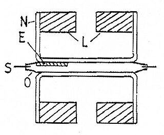
A mechanical filter is a signal processing filter usually used in place of an electronic filter at radio frequencies. Its purpose is the same as that of a normal electronic filter: to pass a range of signal frequencies, but to block others. The filter acts on mechanical vibrations which are the analogue of the electrical signal. At the input and output of the filter, transducers convert the electrical signal into, and then back from, these mechanical vibrations.
An Evans balance, also known as a Johnson Matthey magnetic susceptibility balance, is a scientific instrument used to measure the magnetic susceptibility of solids and liquids. Magnetic susceptibility quantifies the extent to which a material becomes magnetized in an applied magnetic field. It can be measured using various devices that modify the shape of the magnetic field and measure resulting forces. The Evans balance operates by measuring the force exerted on a magnet within a magnetic field shared with a sample as an indirect proxy for the magnetization of a sample, rather than by measuring the force exerted on the sample directly.

A MEMSmagnetic field sensor is a small-scale microelectromechanical systems (MEMS) device for detecting and measuring magnetic fields (magnetometer). Many of these operate by detecting effects of the Lorentz force: a change in voltage or resonant frequency may be measured electronically, or a mechanical displacement may be measured optically. Compensation for temperature effects is necessary. Its use as a miniaturized compass may be one such simple example application.

Magnetic levitation (maglev) or magnetic suspension is a method by which an object is suspended with no support other than magnetic fields. Magnetic force is used to counteract the effects of the gravitational force and any other forces.

A microscanner, or micro scanning mirror, is a microoptoelectromechanical system (MOEMS) in the category of micromirror actuators for dynamic light modulation. Depending upon the type of microscanner, the modulatory movement of a single mirror can be either translatory or rotational, on one or two axes. In the first case, a phase shifting effect takes place. In the second case, the incident light wave is deflected.
An electropermanent magnet or EPM is a type of permanent magnet in which the external magnetic field can be switched on or off by a pulse of electric current in a wire winding around part of the magnet. The magnet consists of two sections, one of "hard" magnetic material and one of "soft" material. The direction of magnetization in the latter piece can be switched by a pulse of current in a wire winding about the former. When the magnetically soft and hard materials have opposing magnetizations, the magnet produces no net external field across its poles, while when their direction of magnetization is aligned the magnet produces an external magnetic field.
A magnetic gear resembles the traditional mechanical gear in geometry and function, using magnets instead of teeth. As two opposing magnets approach each other, they repel; when placed on two rings the magnets will act like teeth. As opposed to conventional hard contact backlash in a spur gear, where a gear may rotate freely until in contact with the next gear, the magnetic gear has a springy backlash. As a result magnetic gears are able to apply pressure no matter the relative angle. Although they provide a motion ratio as a traditional gear, such gears work without touching and are immune to wear of mating surfaces, have no noise, and may slip without damage.


