The NASA 737 research aircraft on the Wallops runway in 1987 with the microwave landing system equipment in the foreground
The microwave landing system (MLS) is an all-weather, precision radio guidance system intended to be installed at large airports to assist aircraft in landing, including 'blind landings'.[1] MLS enables an approaching aircraft to determine when it is aligned with the destination runway and on the correct glidepath for a safe landing. MLS was intended to replace or supplement the instrument landing systems (ILS). MLS has a number of operational advantages over ILS, including a wider selection of channels to avoid interference with nearby installations, excellent performance in all weather, a small "footprint" at the airports, and wide vertical and horizontal "capture" angles that allowed approaches from wider areas around the airport.
Although some MLS systems became operational in the 1990s, the widespread deployment envisioned by some aviation agencies never became a reality. There were two reasons: (economic) while technically superior to ILS, MLS did not offer sufficiently greater capabilities to justify adding MLS receivers to aircraft equipage; and (potentially superior third system) GPS-based systems, notably WAAS, allowed the expectation of a similar level of positioning with no equipment needed at the airport. GPS/WAAS dramatically lowers an airport's cost of implementing precision "like" landing approaches, which is particularly important at small airports. For these reasons, most existing MLS systems in North America have been turned off. GPS/WAAS-based LPV 'Localizer Performance with Vertical guidance' approaches provide vertical guidance comparable to ILS Category I and FAA-published LPV approaches currently outnumber ILS approaches at US airports.
Though initially MLS appeared to be of interest in Europe, where concerns over the availability of GPS in Europe were an issue, widespread installation never occurred. Further deployment of the system is not likely. Rather, several European airports have implemented LPV approaches based on the EGNOS (WAAS-compatible) satellite system.
Principle
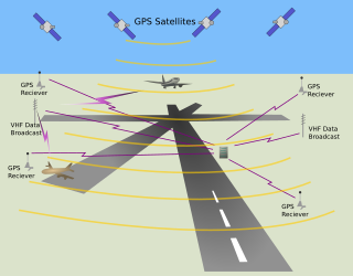
MLS employs 5GHz transmitters at the landing place which use passive electronically scanned arrays to send scanning beams towards approaching aircraft. An aircraft that enters the scanned volume uses a special receiver that calculates its position by measuring the arrival times of the beams.
The US version of MLS, a joint development between the FAA, NASA, and the United States Department of Defense, was designed to provide precision navigation guidance for exact alignment and descent of aircraft on approach to a runway. It provides azimuth, elevation, and distance, as well as "back azimuth" for navigating away from an aborted landing or missed approach. MLS channels were also used for short-range communications with airport controllers, allowing long-distance frequencies to be handed over to other aircraft.
In Australia, design work commenced on a version of MLS in 1972. Most of this work was done jointly by the Federal Department of Civil Aviation (DCA), and the Radio Physics Division of the CSIRO. The project was called Interscan, one of several microwave landing systems under consideration internationally. Interscan was chosen by the FAA in 1975 and by the International Civil Aviation Organization in 1978 as the format to be adopted. An engineered version of the system, called MITAN, was developed by industry (AWA and Hawker de Havilland) under a contract with DCA's successor, the Department of Transport, and successfully demonstrated at Melbourne Airport in the late 1970s. The white antenna dishes could still be seen at Melbourne Airport until 2003 when they were dismantled.
This initial research was followed by the formation of Interscan International limited in Sydney, Australia in 1979 which manufactured MLS systems that were subsequently deployed in the US, EU, Taiwan, China and Australia. The Civil Aviation Authority (United Kingdom) developed a version of MLS, which is installed at Heathrow Airport and other airports, because of the greater incidence of instrument approaches with Cat II/III weather.
An MLS azimuth guidance station with rectangular azimuth scanning antenna with DME antenna at left
Compared with the existing instrument landing system (ILS), MLS had significant advantages. The antennas were much smaller, using a higher frequency signal. They also did not have to be placed at a specific location at the airport, and could "offset" their signals electronically. This made placement easier compared with the physically larger ILS systems, which had to be placed at the ends of the runways and along the approach path.
Another advantage was that the MLS signals covered a very wide fan-shaped area off the end of the runway, allowing controllers to direct aircraft approaching from a variety of directions or guide aircraft along a segmented approach. In comparison, ILS could only guide the aircraft down a single straight line, requiring controllers to distribute planes along that line. MLS allowed aircraft to approach from whatever direction they were already flying in, as opposed to flying to a parking orbit before "capturing" the ILS signal. This was particularly valuable at larger airports, as it could allow the aircraft to be separated horizontally much closer to the airport. Similarly in elevation, the fan shaped coverage allows for variations in descent rate, making MLS useful for aircraft with steeper approach angles such as helicopters, fighters and the space shuttle.
An MLS elevation guidance station
Unlike ILS, which required a variety of frequencies to broadcast the various signals, MLS used a single frequency, broadcasting the azimuth and altitude information one after the other. This reduced the chance of frequency conflicts, as did the fact that the frequencies used were far away from FM broadcasts, another problem with ILS. MLS also offered two hundred separate channels, making conflicts between airports in the same area easily preventable.
Finally, the accuracy was greatly improved over ILS. For instance, standard DME equipment used with ILS offered range accuracy of only ±1200 feet. MLS improved this to ±100ft in what they referred to as DME/P (for precision), and offered similar improvements in azimuth and altitude. This allowed MLS to guide extremely accurate CAT III approaches, whereas this normally required an expensive ground-based high precision radar.
Similar to other precision landing systems, lateral and vertical guidance may be displayed on conventional course deviation indicators or incorporated into multipurpose cockpit displays. Range information can also be displayed by conventional DME indicators and also incorporated into multipurpose displays.
It was originally intended that ILS would remain in operation until 2010 before being replaced by MLS. The system was only being installed experimentally in the 1980s when the FAA began to favor GPS. Even in the worst cases, GPS offered at least 300ft accuracy, not as good as MLS, but much better than ILS. GPS also worked "everywhere", not just off the end of the runways. This meant that a single navigation instrument could replace both short and long-range navigation systems, offer better accuracy than either, and required no ground-based equipment.
The performance of GPS, namely vertical guidance accuracy near the runway threshold and the integrity of the system have not been able to match historical ICAO standards and practices. Greater GPS accuracy could be provided by sending out "correcting signals" from ground-based stations, which would improve the accuracy to about 10 m in the worst case, far outperforming MLS. Initially it was planned to send these signals out over short-range FM transmissions on commercial radio frequencies, but this proved to be too difficult to arrange. Today a similar signal is instead sent across all of North America via commercial satellites, in a system known as WAAS. However WAAS is not capable of providing CAT II or CAT III standard signals for air carrier autoland (though WAAS approaches can provide accurate enough guidance for emergency autoland capability in aircraft so equipped using Garmin Autoland) and so a Local Area Augmentation System, or LAAS, must be used.
Space Shuttle
The microwave scanning beam landing system (MSBLS) was a Ku band approach and landing navigation aid used by NASA's Space Shuttle.[2][3][4][5][6] It provided precise elevation, directional and distance data which was used to guide the orbiter for the last two minutes of flight until touchdown. The signal was typically usable from a horizontal distance of approximately 28km and from an altitude of approximately 5km (18,000 feet).
MSBLS installations used by NASA were certified every two years for accuracy. From 2004, the Federal Aviation Administration worked with NASA to execute this verification. Previously, only NASA aircraft and equipment were used. Testing of the Kennedy Space Center's MSBLS in 2004 revealed an accuracy of 5 centimeters.
The Space Shuttle landing approach started with a glide slope of 19 degrees, which is over six times steeper than the typical 3-degree slope of commercial jet airliners.
Operational Functions
The system may be divided into five functions: Approach azimuth, Back azimuth, Approach elevation, Range and Data communications.
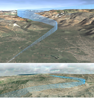
FIG 1-1-10: 3D representation of coverage volumes
Approach azimuth guidance
FIG 1-1-8: Coverage volume of the azimuth stationFIG 1-1-9: Coverage volumes of the elevation station
The azimuth station transmits MLS angle and data on one of 200 channels within the frequency range of 5031 to 5090.7 MHz and is normally located about 1,000 feet (300 m) beyond the stop end of the runway, but there is considerable flexibility in selecting sites. For example, for heliport operations the azimuth transmitter can be collocated with the elevation transmitter.
The azimuth coverage extends: Laterally, at least 40 degrees on either side of the runway centerline in a standard configuration. In elevation, up to an angle of 15 degrees and to at least 20,000 feet (6km), and in range, to at least 20 nautical miles (37km) (See FIG 1-1-8.)
Elevation guidance
The elevation station transmits signals on the same frequency as the azimuth station. A single frequency is time-shared between angle and data functions and is normally located about 400 feet from the side of the runway between runway threshold and the touchdown zone.
Elevation coverage is provided in the same airspace as the azimuth guidance signals: In elevation, to at least +15 degrees; Laterally, to fill the Azimuth lateral coverage and in range, to at least 20 nautical miles (37km) (See FIG 1-1-9.)
Range guidance
The MLS Precision Distance Measuring Equipment (DME/P) functions in the same way as the navigation DME, but there are some technical differences. The beacon transponder operates in the frequency band 962 to 1105MHz and responds to an aircraft interrogator. The MLS DME/P accuracy is improved to be consistent with the accuracy provided by the MLS azimuth and elevation stations.
A DME/P channel is paired with the azimuth and elevation channel. A complete listing of the 200 paired channels of the DME/P with the angle functions is contained in FAA Standard 022 (MLS Interoperability and Performance Requirements).
The DME/N or DME/P is an integral part of the MLS and is installed at all MLS facilities unless a waiver is obtained. This occurs infrequently and only at outlying, low density airports where marker beacons or compass locators are already in place.
Data communications
The data transmission can include both the basic and auxiliary data words. All MLS facilities transmit basic data. Where needed, auxiliary data can be transmitted. MLS data are transmitted throughout the azimuth (and back azimuth when provided) coverage sectors. Representative data include: Station identification, Exact locations of azimuth, elevation and DME/P stations (for MLS receiver processing functions), Ground equipment performance level; and DME/P channel and status.
MLS identification is a four-letter designation starting with the letter M. It is transmitted in International Morse Code at least six times per minute by the approach azimuth (and back azimuth) ground equipment.[7]
Auxiliary data content: Representative data include: 3-D locations of MLS equipment, Waypoint coordinates, Runway conditions and Weather (e.g., RVR, ceiling, altimeter setting, wind, wake vortex, wind shear).
Future
In the United States, the FAA suspended the MLS program in 1994 in favor of the GPS (Wide Area Augmentation System WAAS). The FAA's inventory of instrument flight procedures no longer includes any MLS locations;[8] the last two were eliminated in 2008.[citation needed]
Due to different operational conditions in Europe many countries (particularly those known for low visibility conditions) were expected to embrace the MLS system as a replacement to ILS. However, in reality the only major installation was London Heathrow Airport, which was decommissioned on 31 May 2017. Other major airports, such as Frankfurt Airport which were expected to install MLS have instead installed ground-based augmentation system (GBAS) systems and published GBAS-based approach procedures.[9][10]
As more GBAS system are installed, then the further installation of MLS or continued operation of existing systems must be in doubt.[11]
Radio navigation or radionavigation is the application of radio waves to determine a position of an object on the Earth, either the vessel or an obstruction. Like radiolocation, it is a type of radiodetermination.
The European Geostationary Navigation Overlay Service (EGNOS) is a satellite-based augmentation system (SBAS) developed by the European Space Agency and EUROCONTROL on behalf of the European Commission. Currently, it supplements GPS by reporting on the reliability and accuracy of their positioning data and sending out corrections. The system will supplement Galileo in the future version 3.0.
In aviation, the instrument landing system (ILS) is a precision radio navigation system that provides short-range guidance to aircraft to allow them to approach a runway at night or in bad weather. In its original form, it allows an aircraft to approach until it is 200 feet (61 m) over the ground, within a 1⁄2 mile (800 m) of the runway. At that point the runway should be visible to the pilot; if it is not, they perform a missed approach. Bringing the aircraft this close to the runway dramatically increases the range of weather conditions in which a safe landing can be made. Other versions of the system, or "categories", have further reduced the minimum altitudes, runway visual ranges (RVRs), and transmitter and monitoring configurations designed depending on the normal expected weather patterns and airport safety requirements.
A non-directional beacon (NDB) or non-directional radio beacon is a radio beacon which does not include inherent directional information. Radio beacons are radio transmitters at a known location, used as an aviation or marine navigational aid. NDB are in contrast to directional radio beacons and other navigational aids, such as low-frequency radio range, VHF omnidirectional range (VOR) and tactical air navigation system (TACAN).
Very High Frequency Omnidirectional Range Station (VOR) is a type of short-range VHF radio navigation system for aircraft, enabling aircraft with a VOR receiver to determine the azimuth, referenced to magnetic north, between the aircraft to/from fixed VOR ground radio beacons. VOR and the first DME(1950) system to provide the slant range distance, were developed in the United States as part of a U.S. civil/military programm for Aeronautical Navigation Aids in 1945. Deployment of VOR and DME(1950) began in 1949 by the U.S. CAA. ICAO standardized VOR and DME(1950) in 1950 in ICAO Annex ed.1. Frequencies for the use of VOR are standardized in the very high frequency (VHF) band between 108.00 and 117.95 MHz Chapter 3, Table A. To improve azimuth accuracy of VOR even under difficult siting conditions, Doppler VOR (DVOR) was developed in the 1960s. VOR is according to ICAO rules a primary means navigation system for commercial and general aviation, (D)VOR are gradually decommissioned and replaced by DME-DME RNAV 7.2.3 and satellite based navigation systems such as GPS in the early 21st century. In 2000 there were about 3,000 VOR stations operating around the world, including 1,033 in the US, but by 2013 the number in the US had been reduced to 967. The United States is decommissioning approximately half of its VOR stations and other legacy navigation aids as part of a move to performance-based navigation, while still retaining a "Minimum Operational Network" of VOR stations as a backup to GPS. In 2015, the UK planned to reduce the number of stations from 44 to 19 by 2020.
In aviation, distance measuring equipment (DME) is a radio navigation technology that measures the slant range (distance) between an aircraft and a ground station by timing the propagation delay of radio signals in the frequency band between 960 and 1215 megahertz (MHz). Line-of-visibility between the aircraft and ground station is required. An interrogator (airborne) initiates an exchange by transmitting a pulse pair, on an assigned 'channel', to the transponder ground station. The channel assignment specifies the carrier frequency and the spacing between the pulses. After a known delay, the transponder replies by transmitting a pulse pair on a frequency that is offset from the interrogation frequency by 63 MHz and having specified separation.
The Wide Area Augmentation System (WAAS) is an air navigation aid developed by the Federal Aviation Administration to augment the Global Positioning System (GPS), with the goal of improving its accuracy, integrity, and availability. Essentially, WAAS is intended to enable aircraft to rely on GPS for all phases of flight, including precision approaches to any airport within its coverage area. It may be further enhanced with the Local Area Augmentation System (LAAS) also known by the preferred ICAO term Ground-Based Augmentation System (GBAS) in critical areas.
A tactical air navigation system, commonly referred to by the acronym TACAN, is a navigation system initially designed for naval aircraft to acquire moving landing platforms and later expanded for use by other military aircraft. It provides the user with bearing and distance to a ground or ship-borne station. It is, from an end-user perspective, a more accurate version of the VOR/DME system that provides bearing and range information for civil aviation. The DME portion of the TACAN system is available for civil use; at VORTAC facilities where a VOR is combined with a TACAN, civil aircraft can receive VOR/DME readings. Aircraft equipped with TACAN avionics can use this system for enroute navigation as well as non-precision approaches to landing fields. However, a TACAN-only equipped aircraft cannot receive bearing information from a VOR-only station.
In aviation, an instrument approach or instrument approach procedure (IAP) is a series of predetermined maneuvers for the orderly transfer of an aircraft operating under instrument flight rules from the beginning of the initial approach to a landing, or to a point from which a landing may be made visually. These approaches are approved in the European Union by EASA and the respective country authorities and in the United States by the FAA or the United States Department of Defense for the military. The ICAO defines an instrument approach as "a series of predetermined maneuvers by reference to flight instruments with specific protection from obstacles from the initial approach fix, or where applicable, from the beginning of a defined arrival route to a point from which a landing can be completed and thereafter, if landing is not completed, to a position at which holding or en route obstacle clearance criteria apply."
A marker beacon is a particular type of VHF radio beacon used in aviation, usually in conjunction with an instrument landing system (ILS), to give pilots a means to determine position along an established route to a destination such as a runway.
The local-area augmentation system (LAAS) is an all-weather aircraft landing system based on real-time differential correction of the GPS signal. Local reference receivers located around the airport send data to a central location at the airport. This data is used to formulate a correction message, which is then transmitted to users via a VHF Data Link. A receiver on an aircraft uses this information to correct GPS signals, which then provides a standard instrument landing system (ILS)-style display to use while flying a precision approach. The FAA has stopped using the term LAAS and has transitioned to the International Civil Aviation Organization (ICAO) terminology of ground-based augmentation system (GBAS). While the FAA has indefinitely delayed plans for federal GBAS acquisition, the system can be purchased by airports and installed as a Non-Federal navigation aid.
A transponder landing system (TLS) is an all-weather, precision landing system that uses existing airborne transponder and instrument landing system (ILS) equipment to create a precision approach at a location where an ILS would normally not be available.
Required navigation performance (RNP) is a type of performance-based navigation (PBN) that allows an aircraft to fly a specific path between two 3D-defined points in space.
In the United States Armed Forces, the joint precision approach and landing system (JPALS) is an all-weather system for precision guidance of landing aircraft. It is based on real-time differential correction of the Global Positioning System (GPS) signal, augmented with a local area correction message, and transmitted to the user via secure means. It is used on terrestrial airfields as well as the US Navy's amphibious assault ships and aircraft carriers.
Augmentation of a global navigation satellite system (GNSS) is a method of improving the navigation system's attributes, such as precision, reliability, and availability, through the integration of external information into the calculation process. There are many such systems in place, and they are generally named or described based on how the GNSS sensor receives the external information. Some systems transmit additional information about sources of error, others provide direct measurements of how much the signal was off in the past, while a third group provides additional vehicle information to be integrated in the calculation process.
In aviation, a ground-controlled approach (GCA) is a type of service provided by air-traffic controllers whereby they guide aircraft to a safe landing, including in adverse weather conditions, based on primary radar images. Most commonly, a GCA uses information from either a precision approach radar or an airport surveillance radar. The term GCA may refer to any type of ground radar guided approach such as a PAR, PAR without glideslope or ASR. When both vertical and horizontal guidance from the PAR is given, the approach is termed a precision approach. If no PAR glidepath is given, even if PAR equipment is used for lateral guidance, it is considered a non-precision approach.
The Capstone Program was a United States government-funded aviation safety program for the state of Alaska, primarily focusing on rural areas of the state. This joint effort – between the Federal Aviation Administration (FAA), the Alaska Pilot's Association, commercial operators, the University of Alaska, MITRE Corporation, some avionics manufacturers and individual pilots – cut the accident rate in the eastern part of Alaska by around 40%.
In aeronautics, the final approach is the last leg in an aircraft's approach to landing, when the aircraft is lined up with the runway and descending for landing. In aviation radio terminology, it is often shortened to "final".
Localizer performance with vertical guidance (LPV) are the highest precision GPS aviation instrument approach procedures currently available without specialized aircrew training requirements, such as required navigation performance (RNP). Landing minima are usually similar to those of a Cat I instrument landing system (ILS), that is, a decision height of 200 feet (61 m) and visibility of 800 m. Lateral guidance is equivalent to a localizer, and uses a ground-independent electronic glide path. Thus, the decision altitude, DA, can be as low as 200 feet. An LPV approach is an approach with vertical guidance, APV, to distinguish it from a precision approach, PA, or a non-precision approach, NPA. SBAS criteria includes a vertical alarm limit more than 12 m, but less than 50 m, yet an LPV does not meet the ICAO Annex 10 precision approach standard.
An enhanced flight vision system is an airborne system which provides an image of the scene and displays it to the pilot, in order to provide an image in which the scene and objects in it can be better detected. In other words, an EFVS is a system which provides the pilot with an image which is better than unaided human vision. An EFVS includes imaging sensors such as a color camera, infrared camera or radar, and typically a display for the pilot, which can be a head-mounted display or head-up display. An EFVS may be combined with a synthetic vision system to create a combined vision system.
References
↑ ICAO Annex 10, Volume I, Chapter 3, Section 3.11 Microwave Landing Systems Characteristics (7ed.). Montreal: International Civil Aviation Organisation. 2018.
This page is based on this Wikipedia article Text is available under the CC BY-SA 4.0 license; additional terms may apply. Images, videos and audio are available under their respective licenses.