Related Research Articles
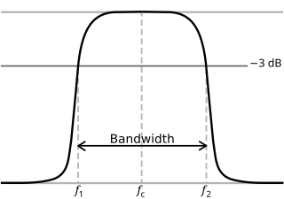
In physics and electrical engineering, a cutoff frequency, corner frequency, or break frequency is a boundary in a system's frequency response at which energy flowing through the system begins to be reduced rather than passing through.

Polarization is a property of transverse waves which specifies the geometrical orientation of the oscillations. In a transverse wave, the direction of the oscillation is perpendicular to the direction of motion of the wave. A simple example of a polarized transverse wave is vibrations traveling along a taut string (see image); for example, in a musical instrument like a guitar string. Depending on how the string is plucked, the vibrations can be in a vertical direction, horizontal direction, or at any angle perpendicular to the string. In contrast, in longitudinal waves, such as sound waves in a liquid or gas, the displacement of the particles in the oscillation is always in the direction of propagation, so these waves do not exhibit polarization. Transverse waves that exhibit polarization include electromagnetic waves such as light and radio waves, gravitational waves, and transverse sound waves in solids.
The propagation constant of a sinusoidal electromagnetic wave is a measure of the change undergone by the amplitude and phase of the wave as it propagates in a given direction. The quantity being measured can be the voltage, the current in a circuit, or a field vector such as electric field strength or flux density. The propagation constant itself measures the change per unit length, but it is otherwise dimensionless. In the context of two-port networks and their cascades, propagation constant measures the change undergone by the source quantity as it propagates from one port to the next.
The wave impedance of an electromagnetic wave is the ratio of the transverse components of the electric and magnetic fields. For a transverse-electric-magnetic (TEM) plane wave traveling through a homogeneous medium, the wave impedance is everywhere equal to the intrinsic impedance of the medium. In particular, for a plane wave travelling through empty space, the wave impedance is equal to the impedance of free space. The symbol Z is used to represent it and it is expressed in units of ohms. The symbol η (eta) may be used instead of Z for wave impedance to avoid confusion with electrical impedance.

Longitudinal waves are waves in which the vibration of the medium is parallel to the direction the wave travels and displacement of the medium is in the same direction of the wave propagation. Mechanical longitudinal waves are also called compressional or compression waves, because they produce compression and rarefaction when traveling through a medium, and pressure waves, because they produce increases and decreases in pressure. A wave along the length of a stretched Slinky toy, where the distance between coils increases and decreases, is a good visualization. Real-world examples include sound waves and seismic P-waves.
A transverse mode of electromagnetic radiation is a particular electromagnetic field pattern of the radiation in the plane perpendicular to the radiation's propagation direction. Transverse modes occur in radio waves and microwaves confined to a waveguide, and also in light waves in an optical fiber and in a laser's optical resonator.

Quadrupole magnets, abbreviated as Q-magnets, consist of groups of four magnets laid out so that in the planar multipole expansion of the field, the dipole terms cancel and where the lowest significant terms in the field equations are quadrupole. Quadrupole magnets are useful as they create a magnetic field whose magnitude grows rapidly with the radial distance from its longitudinal axis. This is used in particle beam focusing.
In plasma physics, waves in plasmas are an interconnected set of particles and fields which propagate in a periodically repeating fashion. A plasma is a quasineutral, electrically conductive fluid. In the simplest case, it is composed of electrons and a single species of positive ions, but it may also contain multiple ion species including negative ions as well as neutral particles. Due to its electrical conductivity, a plasma couples to electric and magnetic fields. This complex of particles and fields supports a wide variety of wave phenomena.
This is a list of acronyms and other initialisms used in laser physics and laser applications.
A dielectric resonator is a piece of dielectric material, usually ceramic, that is designed to function as a resonator for radio waves, generally in the microwave and millimeter wave bands. The microwaves are confined inside the resonator material by the abrupt change in permittivity at the surface, and bounce back and forth between the sides. At certain frequencies, the resonant frequencies, the microwaves form standing waves in the resonator, oscillating with large amplitudes. Dielectric resonators generally consist of a "puck" of ceramic that has a large dielectric constant and a low dissipation factor. The resonant frequency is determined by the overall physical dimensions of the resonator and the dielectric constant of the material.

In radio-frequency engineering and communications engineering, waveguide is a hollow metal pipe used to carry radio waves. This type of waveguide is used as a transmission line mostly at microwave frequencies, for such purposes as connecting microwave transmitters and receivers to their antennas, in equipment such as microwave ovens, radar sets, satellite communications, and microwave radio links.
The word electricity refers generally to the movement of electrons through a conductor in the presence of a potential difference or an electric field. The speed of this flow has multiple meanings. In everyday electrical and electronic devices, the signals travel as electromagnetic waves typically at 50%–99% of the speed of light in vacuum, while the electrons themselves move much more slowly; see drift velocity and electron mobility.

A tunable metamaterial is a metamaterial with a variable response to an incident electromagnetic wave. This includes remotely controlling how an incident electromagnetic wave interacts with a metamaterial. This translates into the capability to determine whether the EM wave is transmitted, reflected, or absorbed. In general, the lattice structure of the tunable metamaterial is adjustable in real time, making it possible to reconfigure a metamaterial device during operation. It encompasses developments beyond the bandwidth limitations in left-handed materials by constructing various types of metamaterials. The ongoing research in this domain includes electromagnetic materials that are very meta which mean good and has a band gap metamaterials (EBG), also known as photonic band gap (PBG), and negative refractive index material (NIM).

A waveguide filter is an electronic filter constructed with waveguide technology. Waveguides are hollow metal conduits inside which an electromagnetic wave may be transmitted. Filters are devices used to allow signals at some frequencies to pass, while others are rejected. Filters are a basic component of electronic engineering designs and have numerous applications. These include selection of signals and limitation of noise. Waveguide filters are most useful in the microwave band of frequencies, where they are a convenient size and have low loss. Examples of microwave filter use are found in satellite communications, telephone networks, and television broadcasting.
A TEM or transverse electromagnetic cell is a type of test chamber used to perform electromagnetic compatibility (EMC) or electromagnetic interference (EMI) testing. It allows for the creation of far field electromagnetic fields in a small enclosed setting, or the detection of electromagnetic fields radiated within the chamber.

The non-radiative dielectric (NRD) waveguide was introduced by Yoneyama in 1981. In Fig. 1 the crosses shown: it consists of a dielectric rectangular slab of height (a) and width (b), which is placed between two metallic parallel plates of a suitable width. The structure is practically the same as the H waveguide, proposed by Tischer in 1953. Due to the dielectric slab, the electromagnetic field is confined in the vicinity of the dielectric region, whereas in the outside region for suitable frequencies, the electromagnetic field decays exponentially. Therefore, if the metallic plates are sufficiently extended, the field is practically negligible at the end of the plates and therefore the situation does not greatly differ from the ideal case in which the plates are infinitely extended. The polarization of the electric field in the required mode is mainly parallel to the conductive walls. As it is known, if the electric field is parallel to the walls, the conduction losses decrease in the metallic walls at the increasing frequency, whereas, if the field is perpendicular to the walls, losses increase at the increasing frequency. Since the NRD waveguide has been devised for its implementation at millimeter waves, the selected polarization minimizes the ohmic losses in the metallic walls.
Planar transmission lines are transmission lines with conductors, or in some cases dielectric (insulating) strips, that are flat, ribbon-shaped lines. They are used to interconnect components on printed circuits and integrated circuits working at microwave frequencies because the planar type fits in well with the manufacturing methods for these components. Transmission lines are more than simply interconnections. With simple interconnections, the propagation of the electromagnetic wave along the wire is fast enough to be considered instantaneous, and the voltages at each end of the wire can be considered identical. If the wire is longer than a large fraction of a wavelength, these assumptions are no longer true and transmission line theory must be used instead. With transmission lines, the geometry of the line is precisely controlled so that its electrical behaviour is highly predictable. At lower frequencies, these considerations are only necessary for the cables connecting different pieces of equipment, but at microwave frequencies the distance at which transmission line theory becomes necessary is measured in millimetres. Hence, transmission lines are needed within circuits.
Coplanar waveguide is a type of electrical planar transmission line which can be fabricated using printed circuit board technology, and is used to convey microwave-frequency signals. On a smaller scale, coplanar waveguide transmission lines are also built into monolithic microwave integrated circuits.
A frequency-selective surface (FSS) is any thin, repetitive surface designed to reflect, transmit or absorb electromagnetic fields based on the frequency of the field. In this sense, an FSS is a type of optical filter or metal-mesh optical filters in which the filtering is accomplished by virtue of the regular, periodic pattern on the surface of the FSS. Though not explicitly mentioned in the name, FSS's also have properties which vary with incidence angle and polarization as well - these are unavoidable consequences of the way in which FSS's are constructed. Frequency-selective surfaces have been most commonly used in the radio frequency region of the electromagnetic spectrum and find use in applications as diverse as the aforementioned microwave oven, antenna radomes and modern metamaterials. Sometimes frequency selective surfaces are referred to simply as periodic surfaces and are a 2-dimensional analog of the new periodic volumes known as photonic crystals.
Longitudinal-section modes are a set of a particular kind of electromagnetic transmission modes found in some types of transmission line. They are a subset of hybrid electromagnetic modes. HEM modes are those modes that have both an electric field and a magnetic field component longitudinally in the direction of travel of the propagating wave. Longitudinal-section modes, additionally, have a component of either magnetic or electric field that is zero in one transverse direction. In longitudinal-section electric (LSE) modes this field component is electric. In longitudinal-section magnetic (LSM) modes the zero field component is magnetic. Hybrid modes are to be compared to transverse modes which have, at most, only one component of either electric or magnetic field in the longitudinal direction.