Moving parts

Last updated
A model of an engine's moving parts Engine movingparts.jpg
A model of an engine's moving parts

Machines include both fixed and moving parts. The moving parts have controlled and constrained motions. [1] [2]

Contents

Moving parts are machine components excluding any moving fluids, such as fuel, coolant or hydraulic fluid.[ citation needed ] Moving parts also do not include any mechanical locks, switches, nuts and bolts, screw caps for bottles etc. A system with no moving parts is described as "solid state"[ citation needed ].

Mechanical efficiency and wear

The amount of moving parts in a machine is a factor in its mechanical efficiency. The greater the number of moving parts, the greater the amount of energy lost to heat by friction between those parts. [3] For example, in a modern automobile engine, roughly 7% of the total power obtained from burning the engine's fuel is lost to friction between the engine's moving parts. [4]

Conversely, the fewer the number of moving parts, the greater the efficiency. Machines with no moving parts at all can be very efficient. An electrical transformer, for example, has no moving parts, and its mechanical efficiency is generally above the 90% mark. (The remaining power losses in a transformer are from other causes, including loss to electrical resistance in the copper windings and hysteresis loss and eddy current loss in the iron core.) [5]

Two means are used for overcoming the efficiency losses caused by friction between moving parts. First, moving parts are lubricated. Second, the moving parts of a machine are designed so that they have a small amount of contact with one another. The latter, in its turn, comprises two approaches. A machine can be reduced in size, thereby quite simply reducing the areas of the moving parts that rub against one another; and the designs of the individual components can be modified, changing their shapes and structures to reduce or avoid contact with one another. [4]

Lubrication also reduces wear, as does the use of suitable materials. As moving parts wear out, this can affect the precision of the machine. Designers thus have to design moving parts with this factor in mind, ensuring that if precision over the lifetime of the machine is paramount, that wear is accounted for and, if possible, minimized. (A simple example of this is the design of a simple single-wheel wheelbarrow. A design where the axle is fixed to the barrow arms and the wheel rotates around it is prone to wear which quickly causes wobble, whereas a rotating axle that is attached to the wheel and that rotates upon bearings in the arms does not start to wobble as the axle wears through the arms.) [6]

The scientific and engineering discipline that deals with the lubrication, friction, and wear of moving parts is tribology, an interdisciplinary field that encompasses materials science, mechanical engineering, chemistry, and mechanics. [7]

Failure

As mentioned, wear is a concern for moving parts in a machine. [8] Other concerns that lead to failure include corrosion, [8] erosion, [8] thermal stress and heat generation, [8] vibration, [8] fatigue loading, [8] and cavitation.

Fatigue is related to large inertial forces, and is affected by the type of motion that a moving part has. A moving part that has a uniform rotation motion is subject to less fatigue than a moving part that oscillates back and forth. Vibration leads to failure when the forcing frequency of the machine's operation hits a resonant frequency of one or more moving parts, such as rotating shafts. Designers avoid these problems by calculating the natural frequencies of the parts at design time, and altering the parts to limit or eliminate such resonance.

Yet further factors that can lead to failure of moving parts include failures in the cooling and lubrication systems of a machine. [8]

One final, particular, factor related to failure of moving parts is kinetic energy. The sudden release of the kinetic energy of the moving parts of a machine causes overstress failures if a moving part is impeded in its motion by a foreign object. For example, consider a stone caught on the blades of a fan or propeller, or even the proverbial "spanner/monkey wrench in the works". [8] (See foreign object damage for further discussion of this.)

Kinetic energy of the moving parts of a machine

The kinetic energy of a machine is the sum of the kinetic energies of its individual moving parts. A machine with moving parts can, mathematically, be treated as a connected system of bodies, whose kinetic energies are simply summed. The individual kinetic energies are determined from the kinetic energies of the moving parts' translations and rotations about their axes. [9]

The kinetic energy of rotation of the moving parts can be determined by noting that every such system of moving parts can be reduced to a collection of connected bodies rotating about an instantaneous axis, which form either a ring or a portion of an ideal ring, of radius rotating at revolutions per second. This ideal ring is known as the equivalent flywheel, whose radius is the radius of gyration. The integral of the squares of the radii all the portions of the ring with respect to their mass , also expressible if the ring is modelled as a collection of discrete particles as the sum of the products of those mass and the squares of their radii is the ring's moment of inertia, denoted . The rotational kinetic energy of the whole system of moving parts is , where is the angular velocity of the moving parts about the same axis as the moment of inertia. [9] [10]

The kinetic energy of translation of the moving parts is , where is the total mass and is the magnitude of the velocity. This gives the formula for the total kinetic energy of the moving parts of a machine as . [9] [10]

This engineering diagram (illustrating the principle in kinematic design that using incorrect types/numbers of mechanical linkages can cause fixed parts to wobble ) shows the motion of the wobbling parts with a solid outline of the moving part in one position at one extremity of its motion and a phantom line outline of the part in the position at the other extremity. Exemple lineaire rectiligne et glissiere iso et hyperstatique.svg
This engineering diagram (illustrating the principle in kinematic design that using incorrect types/numbers of mechanical linkages can cause fixed parts to wobble ) shows the motion of the wobbling parts with a solid outline of the moving part in one position at one extremity of its motion and a phantom line outline of the part in the position at the other extremity.

Representing moving parts in engineering diagrams

In technical drawing, moving parts are, conventionally, designated by drawing the solid outline of the part in its main or initial position, with an added outline of the part in a secondary, moved, position drawn with a phantom line (a line comprising "dot-dot-dash" sequences of two short and one long line segments) outline. [11] [12] [13] These conventions are enshrined in several standards from the American National Standards Institute and the American Society of Mechanical Engineers, including ASME Y14.2M published in 1979. [14]

In recent decades, the use of animation has become more practical and widespread in technical and engineering diagrams for the illustration of the motions of moving parts. Animation represents moving parts more clearly and enables them and their motions to be more readily visualized. [15] Furthermore, computer aided design tools allow the motions of moving parts to be simulated, allowing machine designers to determine, for example, whether the moving parts in a given design would obstruct one another's motion or collide by simple visual inspection of the (animated) computer model rather than by the designer performing a numerical analysis directly. [16] [17]

See also

Related Research Articles

Friction Force resisting the relative motion of solid surfaces, fluid layers, and material elements sliding against each other

Friction is the force resisting the relative motion of solid surfaces, fluid layers, and material elements sliding against each other. There are several types of friction:

Mechanical advantage is a measure of the force amplification achieved by using a tool, mechanical device or machine system. The device trades off input forces against movement to obtain a desired amplification in the output force. The model for this is the law of the lever. Machine components designed to manage forces and movement in this way are called mechanisms. An ideal mechanism transmits power without adding to or subtracting from it. This means the ideal mechanism does not include a power source, is frictionless, and is constructed from rigid bodies that do not deflect or wear. The performance of a real system relative to this ideal is expressed in terms of efficiency factors that take into account departures from the ideal.

Simple machine Mechanical device that changes the direction or magnitude of a force

A simple machine is a mechanical device that changes the direction or magnitude of a force. In general, they can be defined as the simplest mechanisms that use mechanical advantage to multiply force. Usually the term refers to the six classical simple machines that were defined by Renaissance scientists:

Steam turbine Machine that uses steam to rotate a shaft

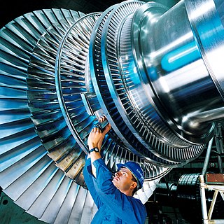
A steam turbine is a machine that extracts thermal energy from pressurized steam and uses it to do mechanical work on a rotating output shaft. Its modern manifestation was invented by Charles Parsons in 1884. Fabrication of a modern steam turbine involves advanced metalwork to form high-grade steel alloys into precision parts using technologies that first became available in the 20th century; continued advances in durability and efficiency of steam turbines remains central to the energy economics of the 21st century.

Turbine Rotary mechanical device that extracts energy from a fluid flow

A turbine is a rotary mechanical device that extracts energy from a fluid flow and converts it into useful work. The work produced by a turbine can be used for generating electrical power when combined with a generator. A turbine is a turbomachine with at least one moving part called a rotor assembly, which is a shaft or drum with blades attached. Moving fluid acts on the blades so that they move and impart rotational energy to the rotor. Early turbine examples are windmills and waterwheels.

Flywheel Mechanical device for storing rotational energy

A flywheel is a mechanical device which uses the conservation of angular momentum to store rotational energy; a form of kinetic energy proportional to the product of its moment of inertia and the square of its rotational speed. In particular, if we assume the flywheel's moment of inertia to be constant then the stored (rotational) energy is directly associated with the square of its rotational speed.

Bearing (mechanical) Mechanism to constrain relative movement to the desired motion and reduce friction

A bearing is a machine element that constrains relative motion to only the desired motion, and reduces friction between moving parts. The design of the bearing may, for example, provide for free linear movement of the moving part or for free rotation around a fixed axis; or, it may prevent a motion by controlling the vectors of normal forces that bear on the moving parts. Most bearings facilitate the desired motion by minimizing friction. Bearings are classified broadly according to the type of operation, the motions allowed, or to the directions of the loads (forces) applied to the parts.

Wear Damaging, gradual removal or deformation of material at solid surfaces

Wear is the damaging, gradual removal or deformation of material at solid surfaces. Causes of wear can be mechanical or chemical. The study of wear and related processes is referred to as tribology.

Tribology is the science and engineering of interacting surfaces in relative motion. It includes the study and application of the principles of friction, lubrication, and wear. Tribology is highly interdisciplinary, drawing on many academic fields, including physics, chemistry, materials science, mathematics, biology, and engineering. People who work in the field of tribology are referred to as tribologists.

Rolling-element bearing

A rolling-element bearing, also known as a rolling bearing, is a bearing which carries a load by placing rolling elements between two bearing rings called races. The relative motion of the races causes the rolling elements to roll with very little rolling resistance and with little sliding.

Mechanical energy Potential and kinetic energy associated with the position and movement of a physical object

In physical sciences, mechanical energy is the sum of potential energy and kinetic energy. It is the macroscopic energy associated with a system. The principle of conservation of mechanical energy states that if an isolated system is subject only to conservative forces, then the mechanical energy is constant. If an object moves in the opposite direction of a conservative net force, the potential energy will increase; and if the speed of the object changes, the kinetic energy of the object also changes. In all real systems, however, nonconservative forces, such as frictional forces, will be present, but if they are of negligible magnitude, the mechanical energy changes little and its conservation is a useful approximation. In elastic collisions, the kinetic energy is conserved, but in inelastic collisions some mechanical energy may be converted into thermal energy. The equivalence between lost mechanical energy (dissipation) and an increase in temperature was discovered by James Prescott Joule.

Bolted joint

Bolted joints are one of the most common elements in construction and machine design. They consist of fasteners that capture and join other parts, and are secured with the mating of screw threads.

Jackscrew Mechanical lifting device operated by turning a leadscrew

A jackscrew, or screw jack, is a type of jack that is operated by turning a leadscrew. It is commonly used to lift moderately and heavy weights, such as vehicles; to raise and lower the horizontal stabilizers of aircraft; and as adjustable supports for heavy loads, such as the foundations of houses.

Centrifugal pump

Centrifugal pumps are used to transport fluids by the conversion of rotational kinetic energy to the hydrodynamic energy of the fluid flow. The rotational energy typically comes from an engine or electric motor. They are a sub-class of dynamic axisymmetric work-absorbing turbomachinery. The fluid enters the pump impeller along or near to the rotating axis and is accelerated by the impeller, flowing radially outward into a diffuser or volute chamber (casing), from which it exits.

Leadscrew

A leadscrew, also known as a power screw or translation screw, is a screw used as a linkage in a machine, to translate turning motion into linear motion. Because of the large area of sliding contact between their male and female members, screw threads have larger frictional energy losses compared to other linkages. They are not typically used to carry high power, but more for intermittent use in low power actuator and positioner mechanisms. Leadscrews are commonly used in linear actuators, machine slides, vises, presses, and jacks. Leadscrews are a common component in electric linear actuators.

Rotational–vibrational coupling

Rotational–vibrational coupling occurs when the rotation frequency of an object is close to or identical to a natural internal vibration frequency. The animation on the right shows a simple example. The motion depicted in the animation is for the idealized situation that the force exerted by the spring increases linearly with the distance to the center of rotation. Also, the animation depicts what would occur if there would not be any friction.

Ball screw Low friction linear actuator

A ball screw is a mechanical linear actuator that translates rotational motion to linear motion with little friction. A threaded shaft provides a helical raceway for ball bearings which act as a precision screw. As well as being able to apply or withstand high thrust loads, they can do so with minimum internal friction. They are made to close tolerances and are therefore suitable for use in situations in which high precision is necessary. The ball assembly acts as the nut while the threaded shaft is the screw. In contrast to conventional leadscrews, ballscrews tend to be rather bulky, due to the need to have a mechanism to re-circulate the balls.

Screw (simple machine) Mechanism that converts rotational motion to linear motion, and a torque (rotational force) to a linear force; one of the six classical simple machines

A screw is a mechanism that converts rotational motion to linear motion, and a torque to a linear force. It is one of the six classical simple machines. The most common form consists of a cylindrical shaft with helical grooves or ridges called threads around the outside. The screw passes through a hole in another object or medium, with threads on the inside of the hole that mesh with the screw's threads. When the shaft of the screw is rotated relative to the stationary threads, the screw moves along its axis relative to the medium surrounding it; for example rotating a wood screw forces it into wood. In screw mechanisms, either the screw shaft can rotate through a threaded hole in a stationary object, or a threaded collar such as a nut can rotate around a stationary screw shaft. Geometrically, a screw can be viewed as a narrow inclined plane wrapped around a cylinder.

Automatic generation control

In an electric power system, automatic generation control (AGC) is a system for adjusting the power output of multiple generators at different power plants, in response to changes in the load. Since a power grid requires that generation and load closely balance moment by moment, frequent adjustments to the output of generators are necessary. The balance can be judged by measuring the system frequency; if it is increasing, more power is being generated than used, which causes all the machines in the system to accelerate. If the system frequency is decreasing, more load is on the system than the instantaneous generation can provide, which causes all generators to slow down.

Most of the terms listed in Wikipedia glossaries are already defined and explained within Wikipedia itself. However, glossaries like this one are useful for looking up, comparing and reviewing large numbers of terms together. You can help enhance this page by adding new terms or writing definitions for existing ones.

References

  1. V B Bhandari (2001). Introduction to machine design. Tata McGraw-Hill. p. 1. ISBN   9780070434493.
  2. Thomas Minchin Goodeve (March 2007). The Elements of Mechanism (Read Books 2007 reprint ed.). London: Longman, Green, Longman, and Roberts. p. 1. ISBN   9781406700497.
  3. Alden J. Balmer (2008). Doc Fizzix Mousetrap Racers: The Complete Builder's Manual. Fox Chapel Publishing. p. 32. ISBN   9781565233591.
  4. 1 2 Steven T. Moeller (2002). Energy efficiency: issues and trends. Nova Publishers. p. 57. ISBN   9781590332016.
  5. Trevor Linsley (2008). Advanced Electrical Installation Work (5th ed.). Newnes. pp.  216. ISBN   9780750687522.
  6. 1 2 Edgar Bright Wilson (1952). An introduction to scientific research. Dover books explaining science (1991 reprint ed.). Courier Dover Publications. pp. 104–105, 108. ISBN   9780486665450.
  7. Wakelin, R. J. (1974). "Tribology: The friction, lubrication, and wear of moving parts". Annual Review of Materials Science . 4: 221–253. Bibcode:1974AnRMS...4..221W. doi:10.1146/annurev.ms.04.080174.001253.
  8. 1 2 3 4 5 6 7 8 M. T. Todinov (2007). Risk-based reliability analysis and generic principles for risk reduction . Elsevier. pp.  208–209. ISBN   9780080447285.
  9. 1 2 3 Russell C. Hibbeler (2009). Engineering Mechanics: Dynamics (12th ed.). Prentice Hall. pp. 457–458. ISBN   9780136077916.
  10. 1 2 James Henry Cotterill (1884). Applied Mechanics. An Elementary General Introduction to the Theory of Structures and Machines. With Diagrams, Illustrations, and Examples (Adegi Graphics LLC reprint ed.). London: Macmillan & Co. pp. 212–215. ISBN   9781421257013.
  11. Jack Lo & David Pressman (2007). How to Make Patent Drawings: A Patent It Yourself Companion (5th ed.). Nolo. pp.  226. ISBN   9781413306538.
  12. David A. Madsen (2001). Engineering drawing and design. Delmar drafting series (3rd ed.). Cengage Learning. p. 48. ISBN   9780766816343.
  13. Cecil Howard Jensen & Jay D. Helsel (1985). Fundamentals of engineering drawing (2nd ed.). Gregg Division, McGraw-Hill. pp.  28. ISBN   9780070325340.
  14. Paul H. Wright (2002). Introduction to engineering. Wiley Desktop Editions Series (3rd ed.). John Wiley and Sons. pp.  155–156, 171. ISBN   9780471059202.
  15. David L. Goetsch; William Chalk; John A. Nelson (1999). Technical drawing. Delmar technical graphics series (4th ed.). Cengage Learning. pp. 452, 456. ISBN   9780766805316.
  16. Peter P. Comninos (1989). "Computer Graphics and Animation for Interior and Industrial Designers". In John Lansdown; Rae A. Earnshaw (eds.). Computers in art, design, and animation . Springer. pp.  216–217. ISBN   9780387968964.
  17. Philip Steadman (1989). "Computer Assistance to the Design Process". In John Lansdown; Rae A. Earnshaw (eds.). Computers in art, design, and animation . Springer. pp.  158. ISBN   9780387968964.

Further reading