Vector sum of all forces acting upon a particle or body
A free body diagram of a block resting on a rough inclined plane, with its weight (W), normal reaction (N) and friction (F) shown.
In mechanics, the net force is the sum of all the forces acting on an object. For example, if two forces are acting upon an object in opposite directions, and one force is greater than the other, the forces can be replaced with a single force that is the difference of the greater and smaller force. That force is the net force.[1]
When forces act upon an object, they change its acceleration. The net force is the combined effect of all the forces on the object's acceleration, as described by Newton's second law of motion.
When the net force is applied at a specific point on an object, the associated torque can be calculated. The sum of the net force and torque is called the resultant force, which causes the object to rotate in the same way as all the forces acting upon it would if they were applied individually.[2]
It is possible for all the forces acting upon an object to produce no torque at all. This happens when the net force is applied along the line of action.
In some texts, the terms resultant force and net force are used as if they mean the same thing. This is not always true, especially in complex topics like the motion of spinning objects or situations where everything is perfectly balanced, known as static equilibrium. In these cases, it is important to understand that "net force" and "resultant force" can have distinct meanings.
Concept
In physics, a force is considered a vector quantity. This means that it not only has a size (or magnitude) but also a direction in which it acts. We typically represent force with the symbol F in boldface, or sometimes, we place an arrow over the symbol to indicate its vector nature, like this: .
When we need to visually represent a force, we draw a line segment. This segment starts at a point A, where the force is applied, and ends at another point B. This line not only gives us the direction of the force (from A to B) but also its magnitude: the longer the line, the stronger the force.
One of the essential concepts in physics is that forces can be added together, which is the basis of vector addition. This concept has been central to physics since the times of Galileo and Newton, forming the cornerstone of Vector calculus, which came into its own in the late 1800s and early 1900s.[3]
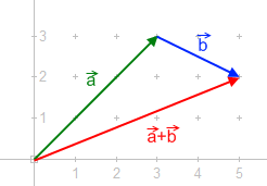
Addition of forces. Note: This picture uses a and b as variables for the vectors which is more common in math focused vector addition. In physics we use F to represent a force so rather than you would write it as .
The picture to the right shows how to add two forces using the "tip-to-tail" method. This method involves drawing forces , and from the tip of the first force. The resulting force, or "total" force, , is then drawn from the start of the first force (the tail) to the end of the second force (the tip). Grasping this concept is fundamental to understanding how forces interact and combine to influence the motion and equilibrium of objects.
When forces are applied to an extended body (a body that's not a single point), they can be applied at different points. Such forces are called 'bound vectors'. It's important to remember that to add these forces together, they need to be considered at the same point.
The concept of "net force" comes into play when you look at the total effect of all of these forces on the body. However, the net force alone may not necessarily preserve the motion of the body. This is because, besides the net force, the 'torque' or rotational effect associated with these forces also matters. The net force must be applied at the right point, and with the right associated torque, to replicate the effect of the original forces.
When the net force and the appropriate torque are applied at a single point, they together constitute what is known as the resultant force. This resultant force-and-torque combination will have the same effect on the body as all the original forces and their associated torques.
A force is known as a bound vector—which means it has a direction and magnitude and a point of application. A convenient way to define a force is by a line segment from a point A to a point B. If we denote the coordinates of these points as A = (Ax, Ay, Az) and B = (Bx, By, Bz), then the force vector applied at A is given by
The length of the vector defines the magnitude of and is given by
The sum of two forces F1 and F2 applied at A can be computed from the sum of the segments that define them. Let F1=B−A and F2=D−A, then the sum of these two vectors is
which can be written as
where E is the midpoint of the segment BD that joins the points B and D.
Thus, the sum of the forces F1 and F2 is twice the segment joining A to the midpoint E of the segment joining the endpoints B and D of the two forces. The doubling of this length is easily achieved by defining a segments BC and DC parallel to AD and AB, respectively, to complete the parallelogram ABCD. The diagonal AC of this parallelogram is the sum of the two force vectors. This is known as the parallelogram rule for the addition of forces.
Translation and rotation due to a force
Point forces
When a force acts on a particle, it is applied to a single point (the particle volume is negligible): this is a point force and the particle is its application point. But an external force on an extended body (object) can be applied to a number of its constituent particles, i.e. can be "spread" over some volume or surface of the body. However, determining its rotational effect on the body requires that we specify its point of application (actually, the line of application, as explained below). The problem is usually resolved in the following ways:
Often, the volume or surface on which the force acts is relatively small compared to the size of the body, so that it can be approximated by a point. It is usually not difficult to determine whether the error caused by such approximation is acceptable.
If it is not acceptable (obviously e.g. in the case of gravitational force), such "volume/surface" force should be described as a system of forces (components), each acting on a single particle, and then the calculation should be done for each of them separately. Such a calculation is typically simplified by the use of differential elements of the body volume/surface, and the integral calculus. In a number of cases, though, it can be shown that such a system of forces may be replaced by a single point force without the actual calculation (as in the case of uniform gravitational force).
In any case, the analysis of the rigid body motion begins with the point force model. And when a force acting on a body is shown graphically, the oriented line segment representing the force is usually drawn so as to "begin" (or "end") at the application point.
Rigid bodies
How a force accelerates a body.
In the example shown in the diagram opposite, a single force acts at the application point H on a free rigid body. The body has the mass and its center of mass is the point C. In the constant mass approximation, the force causes changes in the body motion described by the following expressions:
In the second expression, is the torque or moment of force, whereas is the moment of inertia of the body. A torque caused by a force is a vector quantity defined with respect to some reference point:
is the torque vector, and
is the amount of torque.
The vector is the position vector of the force application point, and in this example it is drawn from the center of mass as the reference point of (see diagram). The straight line segment is the lever arm of the force with respect to the center of mass. As the illustration suggests, the torque does not change (the same lever arm) if the application point is moved along the line of the application of the force (dotted black line). More formally, this follows from the properties of the vector product, and shows that rotational effect of the force depends only on the position of its line of application, and not on the particular choice of the point of application along that line.
The torque vector is perpendicular to the plane defined by the force and the vector , and in this example, it is directed towards the observer; the angular acceleration vector has the same direction. The right-hand rule relates this direction to the clockwise or counterclockwise rotation in the plane of the drawing.
The moment of inertia is calculated with respect to the axis through the center of mass that is parallel with the torque. If the body shown in the illustration is a homogeneous disc, this moment of inertia is . If the disc has the mass 0,5kg and the radius 0,8 m, the moment of inertia is 0,16 kgm2. If the amount of force is 2 N, and the lever arm 0,6 m, the amount of torque is 1,2 Nm. At the instant shown, the force gives to the disc the angular acceleration α = τ/I = 7,5 rad/s2, and to its center of mass it gives the linear acceleration a= F/m= 4m/s2.
Resultant force
Graphical placing of the resultant force.
Resultant force and torque replaces the effects of a system of forces acting on the movement of a rigid body. An interesting special case is a torque-free resultant, which can be found as follows:
Vector addition is used to find the net force;
Use the equation to determine the point of application with zero torque:
where is the net force, locates its application point, and individual forces are with application points . It may be that there is no point of application that yields a torque-free resultant.
The diagram opposite illustrates simple graphical methods for finding the line of application of the resultant force of simple planar systems:
Lines of application of the actual forces and on the leftmost illustration intersect. After vector addition is performed "at the location of ", the net force obtained is translated so that its line of application passes through the common intersection point. With respect to that point all torques are zero, so the torque of the resultant force is equal to the sum of the torques of the actual forces.
The illustration in the middle of the diagram shows two parallel actual forces. After vector addition "at the location of ", the net force is translated to the appropriate line of application, where it becomes the resultant force . The procedure is based on decomposition of all forces into components for which the lines of application (pale dotted lines) intersect at one point (the so-called pole, arbitrarily set at the right side of the illustration). Then the arguments from the previous case are applied to the forces and their components to demonstrate the torque relationships.
The rightmost illustration shows a couple, two equal but opposite forces for which the amount of the net force is zero, but they produce the net torque where is the distance between their lines of application. Since there is no resultant force, this torque can be [is?] described as "pure" torque.
Usage
Vector diagram for addition of non-parallel forces.
In general, a system of forces acting on a rigid body can always be replaced by one force plus one pure (see previous section) torque. The force is the net force, but to calculate the additional torque, the net force must be assigned the line of action. The line of action can be selected arbitrarily, but the additional pure torque depends on this choice. In a special case, it is possible to find such line of action that this additional torque is zero.
The resultant force and torque can be determined for any configuration of forces. However, an interesting special case is a torque-free resultant. This is useful, both conceptually and practically, because the body moves without rotating as if it was a particle.
Some authors do not distinguish the resultant force from the net force and use the terms as synonyms.[4]
↑Symon, Keith R. (1964), Mechanics, Addison-Wesley, LCCN60-5164
↑Michael J. Crowe (1967). A History of Vector Analysis: The Evolution of the Idea of a Vectorial System. Dover Publications (reprint edition; ISBN0-486-67910-1).
↑Resnick, Robert and Halliday, David (1966), Physics, (Vol I and II, Combined edition), Wiley International Edition, Library of Congress Catalog Card No. 66-11527
This page is based on this Wikipedia article Text is available under the CC BY-SA 4.0 license; additional terms may apply. Images, videos and audio are available under their respective licenses.