
An operational amplifier is a DC-coupled electronic voltage amplifier with a differential input, a (usually) single-ended output, and an extremely high gain. Its name comes from its original use of performing mathematical operations in analog computers.
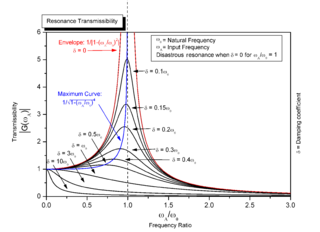
In physics, resonance refers to a wide class of phenomena that arise as a result of matching temporal or spatial periods of oscillatory objects. For an oscillatory dynamical system driven by a time-varying external force, resonance occurs when the frequency of the external force coincides with the natural frequency of the system. Resonance can occur in various systems, such as mechanical, electrical, or acoustic systems, and it is desirable in certain applications, such as musical instruments or radio receivers. Resonance can also be undesirable, leading to excessive vibrations or even structural failure in some cases.
Transistor–transistor logic (TTL) is a logic family built from bipolar junction transistors. Its name signifies that transistors perform both the logic function and the amplifying function, as opposed to earlier resistor–transistor logic (RTL) and diode–transistor logic (DTL).

A rectifier is an electrical device that converts alternating current (AC), which periodically reverses direction, to direct current (DC), which flows in only one direction.

In electromagnetism and electronics, electromotive force is an energy transfer to an electric circuit per unit of electric charge, measured in volts. Devices called electrical transducers provide an emf by converting other forms of energy into electrical energy. Other types of electrical equipment also produce an emf, such as batteries, which convert chemical energy, and generators, which convert mechanical energy. This energy conversion is achieved by physical forces applying physical work on electric charges. However, electromotive force itself is not a physical force, and ISO/IEC standards have deprecated the term in favor of source voltage or source tension instead.
In electrical engineering, electrical elements are conceptual abstractions representing idealized electrical components, such as resistors, capacitors, and inductors, used in the analysis of electrical networks. All electrical networks can be analyzed as multiple electrical elements interconnected by wires. Where the elements roughly correspond to real components, the representation can be in the form of a schematic diagram or circuit diagram. This is called a lumped-element circuit model. In other cases, infinitesimal elements are used to model the network in a distributed-element model.

A negative-feedback amplifier is an electronic amplifier that subtracts a fraction of its output from its input, so that negative feedback opposes the original signal. The applied negative feedback can improve its performance and reduces sensitivity to parameter variations due to manufacturing or environment. Because of these advantages, many amplifiers and control systems use negative feedback.

A power inverter, inverter, or invertor is a power electronic device or circuitry that changes direct current (DC) to alternating current (AC). The resulting AC frequency obtained depends on the particular device employed. Inverters do the opposite of rectifiers which were originally large electromechanical devices converting AC to DC.

The Ćuk converter is a type of buck-boost converter with low ripple current. A Ćuk converter can be seen as a combination of boost converter and buck converter, having one switching device and a mutual capacitor, to couple the energy.
A current mirror is a circuit designed to copy a current through one active device by controlling the current in another active device of a circuit, keeping the output current constant regardless of loading. The current being "copied" can be, and sometimes is, a varying signal current. Conceptually, an ideal current mirror is simply an ideal inverting current amplifier that reverses the current direction as well, or it could consist of a current-controlled current source (CCCS). The current mirror is used to provide bias currents and active loads to circuits. It can also be used to model a more realistic current source.

A current source is an electronic circuit that delivers or absorbs an electric current which is independent of the voltage across it.

The asymptotic gain model is a representation of the gain of negative feedback amplifiers given by the asymptotic gain relation:

A voltage source is a two-terminal device which can maintain a fixed voltage. An ideal voltage source can maintain the fixed voltage independent of the load resistance or the output current. However, a real-world voltage source cannot supply unlimited current.

In electronics, a chopper circuit is any of numerous types of electronic switching devices and circuits used in power control and signal applications. A chopper is a device that converts fixed DC input to a variable DC output voltage directly. Essentially, a chopper is an electronic switch that is used to interrupt one signal under the control of another.
The cascode is a two-stage amplifier that consists of a common emitter stage feeding into a common base stage when using bipolar junction transistors (BJTs) or alternatively a common source stage feeding a common gate stage when using field-effect transistors (FETs).

A boost converter or step-up converter is a DC-to-DC converter that increases voltage, while decreasing current, from its input (supply) to its output (load).
A buck converter or step-down converter is a DC-to-DC converter which decreases voltage, while increasing current, from its input (supply) to its output (load). It is a class of switched-mode power supply. Switching converters provide much greater power efficiency as DC-to-DC converters than linear regulators, which are simpler circuits that dissipate power as heat, but do not step up output current. The efficiency of buck converters can be very high, often over 90%, making them useful for tasks such as converting a computer's main supply voltage, which is usually 12 V, down to lower voltages needed by USB, DRAM and the CPU, which are usually 5, 3.3 or 1.8 V.
Ripple in electronics is the residual periodic variation of the DC voltage within a power supply which has been derived from an alternating current (AC) source. This ripple is due to incomplete suppression of the alternating waveform after rectification. Ripple voltage originates as the output of a rectifier or from generation and commutation of DC power.

In electronics, biasing is the setting of DC operating conditions of an electronic component that processes time-varying signals. Many electronic devices, such as diodes, transistors and vacuum tubes, whose function is processing time-varying (AC) signals, also require a steady (DC) current or voltage at their terminals to operate correctly. This current or voltage is called bias. The AC signal applied to them is superposed on this DC bias current or voltage.

A nullor is a theoretical two-port network consisting of a nullator at its input and a norator at its output. Nullors represent an ideal amplifier, having infinite current, voltage, transconductance and transimpedance gain. Its transmission parameters are all zero, that is, its input–output behavior is summarized with the matrix equation
