General parameters used for constructing nose cone profiles.
Because of the problem of the aerodynamicdesign of the nose cone section of any vehicle or body meant to travel through a compressible fluid medium (such as a rocket or aircraft, missile, shell or bullet), an important problem is the determination of the nose cone geometrical shape for optimum performance. For many applications, such a task requires the definition of a solid of revolution shape that experiences minimal resistance to rapid motion through such a fluid medium.
In all of the following nose cone shape equations, L is the overall length of the nose cone and R is the radius of the base of the nose cone. y is the radius at any point x, as x varies from 0, at the tip of the nose cone, to L. The equations define the two-dimensional profile of the nose shape. The full body of revolution of the nose cone is formed by rotating the profile around the centerline C⁄L. While the equations describe the "perfect" shape, practical nose cones are often blunted or truncated for manufacturing, aerodynamic, or thermodynamic reasons.[1][2]
Conic
Conic nose cone render and profile with parameters shown.
Spherically blunted conic
Spherically blunted conic nose cone render and profile with parameters shown.
Bi-conic
Bi-conic nose cone render and profile with parameters shown.
Tangent ogive
Tangent ogive nose cone render and profile with parameters and ogive circle shown.
Spherically blunted tangent ogive
Spherically blunted tangent ogive nose cone render and profile with parameters shown.
Secant ogive
Secant ogive nose cone render and profile with parameters and ogive circle shown, ogive radius larger than for equivalent tangent ogive.
For a chosen ogive radius ρ greater than or equal to the ogive radius of a tangent ogive with the same R and L:
Alternate secant ogive render and profile which show a bulge due to a smaller radius.
A smaller ogive radius can be chosen; for , you will get the shape shown on the right, where the ogive has a "bulge" on top, i.e. it has more than one x that results in some values of y.
Elliptical
Elliptical nose cone render and profile with parameters shown.
Parabolic
A parabolic series nosecone is defined by where and is a series-specific constant.[3]
Half (K′ = 1/2)
Three-quarter (K′ = 3/4)
Full (K′ = 1)
Renders of common parabolic nose cone shapes.
For ,
K′ can vary anywhere between 0 and 1, but the most common values used for nose cone shapes are:
Parabola type
K′ value
Cone
0
Half
1/2
Three quarter
3/4
Full
1
Power series
A power series nosecone is defined by where . will generate a concave geometry, while will generate a convex (or "flared") shape.[3]
Graphs illustrating power series nose cone shapes
Half (n = 1/2)
Three-quarter (n = 3/4)
For :
Common values of n include:
Power type
n value
Cylinder
0
Half (parabola)
1/2
Three quarter
3/4
Cone
1
Haack series
A Haack series nosecone is defined by where .[3] Parametric formulation can be obtained by solving the formula for .
Graphs illustrating Haack series nose cone shapes
LD-Haack (Von Kármán) (C = 0)
LV-Haack (C = 1/3)
Special values of C (as described above) include:
Haack series type
C value
LD-Haack (Von Kármán)
0
LV-Haack
1/3
Tangent
2/3
Von Kármán ogive
The LD-Haack ogive is a special case of the Haack series with minimal drag for a given length and diameter, and is defined as a Haack series with C = 0, commonly called the Von Kármán or Von Kármán ogive. A cone with minimal drag for a given length and volume can be called an LV-Haack series, defined with .[3]
An aerospike can be used to reduce the forebody pressure acting on supersonic aircraft. The aerospike creates a detached shock ahead of the body, thus reducing the drag acting on the aircraft.
Nose cone drag characteristics
Influence of the general shape
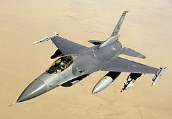
Closeup view of a nose cone on a Boeing 737Comparison of drag characteristics of various nose cone shapes in the transonic to low-mach regions. Rankings are: superior (1), good (2), fair (3), inferior (4).General Dynamics F-16 with a nose cone very close to the Von Kármán shape
This page is based on this Wikipedia article Text is available under the CC BY-SA 4.0 license; additional terms may apply. Images, videos and audio are available under their respective licenses.