Operational View

Last updated
Example of an "Operational View" (OV) on the DoD Electronic Commerce Concept of Operations. DoD Electronic Commerce Concept of Operations (OV-1).jpg
Example of an "Operational View" (OV) on the DoD Electronic Commerce Concept of Operations.

Operational View (OV) is one of the basic views defined in the enterprise architecture (EA) of the Department of Defense Architecture Framework V1.5 (DoDAF) and is related with concept of operations. Under DODAF 2, which became operational in 2009, the collections of views are now termed 'viewpoints' and no longer views.

Contents

Other enterprise architecture frameworks may or do have operational views. For example, the MODAF has an Operational Viewpoint and the NATO Architecture Framework has an Operational View (collection of subviews). This article will further explain the construction of the Operational View of the DoDAF V1.5.

Overview

The "Operational View" (OV) in the DoDAF Enterprise architecture framework (version 1/1.5) ('Operational Viewpoint' in DODAF 2) describes the tasks and activities, operational elements, and information exchanges required to conduct operations. A pure Operational View is material independent. However, operations and their relationships may be influenced by new technologies such as collaboration technology, where process improvements are in practice before policy can reflect the new procedures. [1]

The operational viewpoint provides a means to describe what is needed in a solution-free or implementation-free way. There may be some cases, however, in which it is necessary to document the way processes are performed given the restrictions of current systems, in order to examine ways in which new systems could facilitate streamlining the processes. In such cases, an Operational View may have material constraints and requirements that must be addressed. For this reason, it may be necessary to include some high-level Systems View (SV) architecture data as overlays or augmenting information onto the Operational View products. [1]

Operational View topics

DoDAF

The Department of Defense Architecture Framework (DoDAF) defines a standard way to organize a systems architecture into complementary and consistent views. It is especially suited to large systems with complex integration and interoperability challenges, and is apparently unique in its use of "operational views" detailing the external customer's operating domain in which the developing system will operate.

DoDAF view model shows the linkages among views. DoDAF Linkages Among Views.jpg
DoDAF view model shows the linkages among views.

The DoDAF defines a set of products that act as mechanisms for visualizing, understanding, and assimilating the broad scope and complexities of an architecture description through graphic, tabular, or textual means. These products are organized under four views:

Each view depicts certain perspectives of an architecture as described below. Only a subset of the full DoDAF viewset is usually created for each system development. The figure represents the information that links the operational view, systems and services view, and technical standards view. The three views and their interrelationships driven – by common architecture data elements – provide the basis for deriving measures such as interoperability or performance, and for measuring the impact of the values of these metrics on operational mission and task effectiveness. [2]

OV products

The Department of Defense Architecture Framework (DoDAF) has defined a series of seven different types of Operational View products. [1] There are seven OV products described in this section:

High-Level Operational Concept Graphic

  • High-Level Operational Concept Graphic (OV-1) : High level graphical and textual description of operational concept (high level organizations, missions, geographic configuration, connectivity, etc.).

Operational Node Connectivity Description

  • Operational Node Connectivity Description (OV-2) : Operational nodes, activities performed at each node, and connectivites and information flow between nodes.

Operational Information Exchange Matrix

  • Operational Information Exchange Matrix (OV-3) : Information exchanged between nodes and the relevant attributes of that exchange such as media, quality, quantity, and the level of interoperability required.

Organizational Relationships Chart

  • Organizational Relationships Chart (OV-4) : Command, control, coordination, and other relationships among organizations.

Operational Activity Model

  • Operational Activity Model (OV-5) : Activities, relationships among activities, inputs and outputs. In addition, overlays can show cost, performing nodes, or other pertinent information.

Other OV products

  • Operational Rules Model, State Transition Description, and Event-Trace Description (OV-6a, 6b, and 6c)
    • Operational Rules Model (OV-6a) : One of the three products used to describe operational activity sequence and timing that identifies the business rules that constrain the operation.
    • Operational State Transition Description (OV-6b) : One of the three products used to describe operational activity sequence and timing that identifies responses of a business process to events.
    • Operational Event-Trace Description (OV-6c) : One of the three products used to describe operational activity sequence and timing that traces the actions in a scenario or critical sequence of events.
  • Logical Data Model (OV-7) : Documentation of the data requirements and structural business process rules of the Operational View.

Executable Operational Architecture

Anatomy of an Executable Operational Architecture. Anatomy of an Executable Operational Architecture.jpg
Anatomy of an Executable Operational Architecture.

In addition to examining behavior over time, one can also assess an overall dynamic mission cost over time in terms of human and system/network resource dollar costs and their processes dollar costs. Analysis of dollar costs in executable architectures is a first step in an architecture based investment strategy, where we eventually need to align architectures to funding decisions to ensure that investment decisions are directly linked to mission objectives and their outcomes. The figure on the right illustrates the anatomy of one such dynamic model. [1]

State transitions in executable operational architectural models provide for descriptions of conditions that control the behavior of process events in responding to inputs and in producing outputs. A state specifies the response of a process to events. The response may vary depending on the current state and the rule set or conditions. Distribution settings determine process time executions. Examples of distribution strategies include: constant values, event list, constant interval spacing, normal distribution, exponential distribution, and so forth. Priority determines the processing strategy if two inputs reach a process at the same time. Higher priority inputs are usually processed before lower priority inputs. [1]

Sample Histograms Showing Results of a Simulation Run. Sample Histograms Showing Results of a Simulation Run.jpg
Sample Histograms Showing Results of a Simulation Run.

Processes receiving multiple inputs need to define how to respond. Examples of responses include: process each input in the order of arrival independent of each other, process only when all inputs are available, or process as soon as any input is detected. Processes producing multiple outputs can include probabilities (totaling 100 percent), under which each output would be produced. Histograms are examples of generated timing descriptions. They are graphic representations of processes, human and system resources, and their used capacity over time during a simulation run. These histograms are used to perform dynamic impact analysis of the behavior of the executable architecture. Figure 4-23 is an example showing the results of a simulation run of human resource capacity. [1]

See also

Related Research Articles

<span class="mw-page-title-main">Zachman Framework</span> Structure for enterprise architecture

The Zachman Framework is an enterprise ontology and is a fundamental structure for enterprise architecture which provides a formal and structured way of viewing and defining an enterprise. The ontology is a two dimensional classification schema that reflects the intersection between two historical classifications. The first are primitive interrogatives: What, How, When, Who, Where, and Why. The second is derived from the philosophical concept of reification, the transformation of an abstract idea into an instantiation. The Zachman Framework reification transformations are: identification, definition, representation, specification, configuration and instantiation.

<span class="mw-page-title-main">Business process modeling</span> Activity of representing processes of an enterprise

Business process modeling (BPM), mainly used in business process management; software development, or systems engineering, is the action of capturing and representing processes of an enterprise, so that the current business processes may be analyzed, applied securely and consistently, improved, and automated. BPM is typically orchestrated by business analysts, leveraging their expertise in modeling practices. Subject matter experts, equipped with specialized knowledge of the processes being modeled, often collaborate within these teams. Alternatively, process models can be directly derived from digital traces within IT systems, such as event logs, utilizing process mining tools.

A functional software architecture (FSA) is an architectural model that identifies enterprise functions, interactions and corresponding IT needs. These functions can be used as a reference by different domain experts to develop IT-systems as part of a co-operative information-driven enterprise. In this way, both software engineers and enterprise architects can create an information-driven, integrated organizational environment.

<span class="mw-page-title-main">Department of Defense Architecture Framework</span> Enterprise architecture framework

The Department of Defense Architecture Framework (DoDAF) is an architecture framework for the United States Department of Defense (DoD) that provides visualization infrastructure for specific stakeholders concerns through viewpoints organized by various views. These views are artifacts for visualizing, understanding, and assimilating the broad scope and complexities of an architecture description through tabular, structural, behavioral, ontological, pictorial, temporal, graphical, probabilistic, or alternative conceptual means. The current release is DoDAF 2.02.

<span class="mw-page-title-main">System Architect</span> Enterprise architecture tool

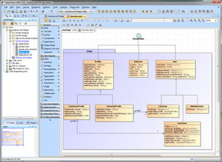
Unicom System Architect is an enterprise architecture tool that is used by the business and technology departments of corporations and government agencies to model their business operations and the systems, applications, and databases that support them. System Architect is used to build architectures using various frameworks including TOGAF, ArchiMate, DoDAF, MODAF, NAF and standard method notations such as sysML, UML, BPMN, and relational data modeling. System Architect is developed by UNICOM Systems, a division of UNICOM Global, a United States-based company.

The British Ministry of Defence Architecture Framework (MODAF) was an architecture framework which defined a standardised way of conducting enterprise architecture, originally developed by the UK Ministry of Defence. It has since been replaced with the NATO Architecture Framework.

The Unified Profile for DoDAF/MODAF (UPDM) is the product of an Object Management Group (OMG) initiative to develop a modeling standard that supports both the USA Department of Defense Architecture Framework (DoDAF) and the UK Ministry of Defence Architecture Framework (MODAF). The current UPDM - the Unified Profile for DoDAF and MODAF was based on earlier work with the same acronym and a slightly different name - the UML Profile for DoDAF and MODAF.

The IDEAS Group is the International Defence Enterprise Architecture Specification for exchange Group. The deliverable of the project is a data exchange format for military Enterprise Architectures. The scope is four nation and covers MODAF (UK), DoDAF (US), DNDAF (Canada) and the Australian Defence Architecture Framework (AUSDAF). The initial scope for exchange is the architectural data required to support coalition operations planning, including:

<span class="mw-page-title-main">MagicDraw</span> Systems modelling software

MagicDraw is a proprietary visual UML, SysML, BPMN, and UPDM modeling tool with team collaboration support.

<span class="mw-page-title-main">RM-ODP</span> Reference model in computer science

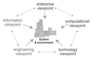
Reference Model of Open Distributed Processing (RM-ODP) is a reference model in computer science, which provides a co-ordinating framework for the standardization of open distributed processing (ODP). It supports distribution, interworking, platform and technology independence, and portability, together with an enterprise architecture framework for the specification of ODP systems.

Object-oriented design (OOD) is the process of planning a system of interacting objects to solve a software problem. It is a method for software design. By defining classes and their functionality for their children, each object can run the same implementation of the class with its state.

AGATE is a framework for modeling computer or communication systems architecture.

A concept of operations is a document describing the characteristics of a proposed system from the viewpoint of an individual who will use that system. Examples include business requirements specification or stakeholder requirements specification (StRS). CONOPS is used to communicate the quantitative and qualitative system characteristics to all stakeholders. CONOPS are widely used in the military, governmental services and other fields.

The first version of the Enterprise Collaboration Architecture (ECA) has been published by the Object Management Group (OMG) in 2001. The vision of the (ECA) is to simplify the development of component based and services oriented systems by providing a modeling framework aligned with the model-driven architecture (MDA) of the Object Management Group (OMG).

<span class="mw-page-title-main">View model</span>

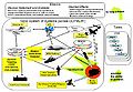
A view model or viewpoints framework in systems engineering, software engineering, and enterprise engineering is a framework which defines a coherent set of views to be used in the construction of a system architecture, software architecture, or enterprise architecture. A view is a representation of the whole system from the perspective of a related set of concerns.

<span class="mw-page-title-main">Treasury Enterprise Architecture Framework</span>

Treasury Enterprise Architecture Framework (TEAF) was an enterprise architecture framework for treasury, based on the Zachman Framework. It was developed by the US Department of the Treasury and published in July 2000. May 2012 this framework has been subsumed by evolving Federal Enterprise Architecture Policy as documented in "The Common Approach to Federal Enterprise Architecture".

<span class="mw-page-title-main">Core architecture data model</span>

Core architecture data model (CADM) in enterprise architecture is a logical data model of information used to describe and build architectures.

A capability, in the systems engineering sense, is defined as the ability to execute a specified course of action. A capability may or may not be accompanied by an intention. The term is used in the defense industry but also in private industry.

<span class="mw-page-title-main">TRAK</span> Enterprise architecture framework

TRAK is a general enterprise architecture framework aimed at systems engineers. It is based on MODAF 1.2.

<span class="mw-page-title-main">Interaction Flow Modeling Language</span>

The Interaction Flow Modeling Language (IFML) is a standardized modeling language in the field of software engineering. IFML includes a set of graphic notations to create visual models of user interactions and front-end behavior in software systems.

References

  1. 1 2 3 4 5 6 7 DoD Architecture Framework Working Group (2003). DoDAF 1.5 Volume 2, 15 August 2003.
  2. 1 2 DoD (2007) DoD Architecture Framework Version 2.0. 28 May 2009