Outboard tail

Last updated
SpaceShipOne at the US National Air and Space Museum Spaceship One at Smithsonian.jpg
SpaceShipOne at the US National Air and Space Museum

An outboard tail is a type of aircraft tail or empennage which is split in two, with each half mounted on a short boom just behind and outboard of each wing tip. It comprises outboard horizontal stabilizers (OHS) and may or may not include additional boom-mounted vertical stabilizers (fins). OHS designs are sometimes described as a form of tailless aircraft.

Contents

The outboard tail surfaces are positioned so that they interact constructively with the wingtip vortices to significantly reduce drag, without causing undue structural or handling difficulties.

Characteristics

Outboard tail Outboard tail.svg
Outboard tail

An outboard tail is located outboard of the main wing tips. Although sometimes described as tailless, the outboard tail configuration differs from a tailless wing in that the horizontal stabilizer is discontinuous from the main wing surface, typically being set further back and requiring a short boom to support it. If the wing is swept, then the boom can be very short and the front of the tail may overlap the rear of the wing. The tail comprises outboard horizontal stabilizers (OHS) and may or may not include additional boom-mounted vertical stabilizers (fins).

A normal wing tip creates a significant trailing vortex, due to an upwash of air spilling up round it from underneath and then moving inwards towards the low pressure region above the wing surface. These vortices can carry away significant amounts of energy, thus increasing drag.

In the outboard tail configuration, the tail surfaces are positioned so that they interact constructively with the upwash behind the wing tips and, with careful design, can significantly reduce drag to improve efficiency, without reducing the handling qualities or adding unduly to the structural loads on the wing. [1] [2]

Compared to a tailless swept wing of similar overall span, the outboard tail has a greater moment arm than if it were attached directly to the wing, while the wing need not sweep back so sharply as to have undesirable side effects. [3]

The outboard elevators can also be used as secondary ailerons, increasing the effective control area. This reduces the variation of loading on the wing during critical manoeuvres such as landing and allows a higher design loading for the wing. This in turn allows greater safety margins when landing. [3]

Vertical tail fins traditionally provide directional stability and control. In outboard configuration they can also enhance airflow and contribute to overall efficiency, in a manner analogous to winglets. [4]

History

Model of the proposed Blohm & Voss P 208.02 ModellPhoto BvP208 zens.png
Model of the proposed Blohm & Voss P 208.02

The configuration was first patented in 1942 by French designer Robert Aimé Robert. [5] It was developed during World War II by German designers Richard Vogt and George Haag at Blohm & Voss. In order to test the proposed control system, Škoda-Kauba adapted the V-6 design as the SK SL6 in 1944. [6]

Blohm & Voss then incorporated the design into the P 208 pusher-engined fighter proposal. Although it was not taken up, modern analysis has shown that it would have been viable. [1] B&V went on to produce a series of design studies and project submissions for similar jet fighters. [7] These included the P 209.01, P 210 and P 212. [8] B&V finally received an order for the P 215 all-weather fighter just weeks before the war ended, so it was never built. [9]

During the late 1950s and early 1960s the principles of the outboard tail were re-investigated by NASA (formerly NACA) engineers, as a part of their research programme into design configurations for supersonic flight. They conducted analyses and wind tunnel model tests at both subsonic and supersonic speeds. [10] [11] [12] [13] [14] Vought studied the layout for their ADAM V/STOL design project. [5]

Further extensive studies were made by J. A. C. Kentfield and colleagues at the University of Calgary, Canada, from the 1990s on. [1]

Burt Rutan at Scaled Composites became interested in the configuration for its potential as a variable-geometry stabiliser on a spaceplane. During atmospheric re-entry from space, the tail would rotate vertically to stabilise the plane, the rest of which remained horizontal but fell near-vertically. His first prototype, the Scaled Composites SpaceShipOne took to the air in 2003. [2] It has since also flown on the improved SpaceShipTwo and forthcoming SpaceShip III.

The outboard tail is also seen as a natural partner to the FanWing concept and a model was flown in 2011. [15] [16]

Related Research Articles

<span class="mw-page-title-main">Delta wing</span> Triangle shaped aircraft wing configuration

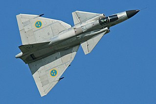
A delta wing is a wing shaped in the form of a triangle. It is named for its similarity in shape to the Greek uppercase letter delta (Δ).

<span class="mw-page-title-main">Flying wing</span> Tailless fixed-wing aircraft that has no definite fuselage

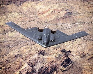
A flying wing is a tailless fixed-wing aircraft that has no definite fuselage, with its crew, payload, fuel, and equipment housed inside the main wing structure. A flying wing may have various small protuberances such as pods, nacelles, blisters, booms, or vertical stabilizers.

<span class="mw-page-title-main">Swept wing</span> Plane wing that angles backwards or forwards

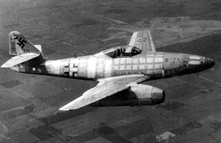
A swept wing is a wing that angles either backward or occasionally forward from its root rather than in a straight sideways direction.

<span class="mw-page-title-main">V-tail</span> Type of aircraft tail

The V-tail or vee-tail of an aircraft is an unconventional arrangement of the tail control surfaces that replaces the traditional vertical and horizontal surfaces with two surfaces set in a V-shaped configuration. It is not widely used in aircraft design. The aft edge of each twin surface is a hinged control surface called a ruddervator, which combines the functions of both a rudder and elevator.

<span class="mw-page-title-main">Stabilator</span>

A stabilator is a fully movable aircraft horizontal stabilizer. It serves the usual functions of longitudinal stability, control and stick force requirements otherwise performed by the separate parts of a conventional horizontal stabilizer and elevator. Apart from reduced drag, particularly at high Mach numbers, it is a useful device for changing the aircraft balance within wide limits, and for reducing stick forces.

<span class="mw-page-title-main">Empennage</span> Tail section of an aircraft containing stabilizers

The empennage, also known as the tail or tail assembly, is a structure at the rear of an aircraft that provides stability during flight, in a way similar to the feathers on an arrow. The term derives from the French language verb empenner which means "to feather an arrow". Most aircraft feature an empennage incorporating vertical and horizontal stabilising surfaces which stabilise the flight dynamics of yaw and pitch, as well as housing control surfaces.

<span class="mw-page-title-main">Airplane</span> Powered, flying vehicle with wings

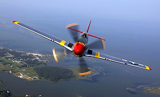
An airplane, or aeroplane, informally plane, is a fixed-wing aircraft that is propelled forward by thrust from a jet engine, propeller, or rocket engine. Airplanes come in a variety of sizes, shapes, and wing configurations. The broad spectrum of uses for airplanes includes recreation, transportation of goods and people, military, and research. Worldwide, commercial aviation transports more than four billion passengers annually on airliners and transports more than 200 billion tonne-kilometers of cargo annually, which is less than 1% of the world's cargo movement. Most airplanes are flown by a pilot on board the aircraft, but some are designed to be remotely or computer-controlled such as drones.

Aircraft flight mechanics are relevant to fixed wing and rotary wing (helicopters) aircraft. An aeroplane, is defined in ICAO Document 9110 as, "a power-driven heavier than air aircraft, deriving its lift chiefly from aerodynamic reactions on surface which remain fixed under given conditions of flight".

The United States Air Force Stability and Control Digital DATCOM is a computer program that implements the methods contained in the USAF Stability and Control DATCOM to calculate the static stability, control and dynamic derivative characteristics of fixed-wing aircraft. Digital DATCOM requires an input file containing a geometric description of an aircraft, and outputs its corresponding dimensionless stability derivatives according to the specified flight conditions. The values obtained can be used to calculate meaningful aspects of flight dynamics.

<span class="mw-page-title-main">Leading-edge cuff</span> Fixed aerodynamic wing device

A leading-edge cuff is a fixed aerodynamic wing device employed on fixed-wing aircraft to improve the stall and spin characteristics. Cuffs may be either factory-designed or an after-market add-on modification.

<span class="mw-page-title-main">Vertical stabilizer</span> Aircraft component

A vertical stabilizer or tail fin is the static part of the vertical tail of an aircraft. The term is commonly applied to the assembly of both this fixed surface and one or more movable rudders hinged to it. Their role is to provide control, stability and trim in yaw. It is part of the aircraft empennage, specifically of its stabilizers.

<span class="mw-page-title-main">Mach tuck</span> Aerodynamic effect

Mach tuck is an aerodynamic effect whereby the nose of an aircraft tends to pitch downward as the airflow around the wing reaches supersonic speeds. This diving tendency is also known as tuck under. The aircraft will first experience this effect at significantly below Mach 1.

<span class="mw-page-title-main">Stabilizer (aeronautics)</span> Aircraft component

An aircraft stabilizer is an aerodynamic surface, typically including one or more movable control surfaces, that provides longitudinal (pitch) and/or directional (yaw) stability and control. A stabilizer can feature a fixed or adjustable structure on which any movable control surfaces are hinged, or it can itself be a fully movable surface such as a stabilator. Depending on the context, "stabilizer" may sometimes describe only the front part of the overall surface.

<span class="mw-page-title-main">Canard (aeronautics)</span> Aircraft configuration in which a small wing is placed in front of the main wing

In aeronautics, a canard is a wing configuration in which a small forewing or foreplane is placed forward of the main wing of a fixed-wing aircraft or a weapon. The term "canard" may be used to describe the aircraft itself, the wing configuration, or the foreplane. Canard wings are also extensively used in guided missiles and smart bombs.

<span class="mw-page-title-main">Tailless aircraft</span> Aircraft whose only horizontal aerodynamic surface is its main wing

In aeronautics, a tailless aircraft is an aircraft with no other horizontal aerodynamic surface besides its main wing. It may still have a fuselage, vertical tail fin, and/or vertical rudder.

<span class="mw-page-title-main">Wing configuration</span> Describes the general shape and layout of an aircraft wing

The wing configuration of a fixed-wing aircraft is its arrangement of lifting and related surfaces.

<span class="mw-page-title-main">Blohm & Voss P 208</span> Type of aircraft

The Blohm & Voss P.208 was a design project for a tailless swept-wing propeller-powered interceptor designed by the German company Blohm & Voss towards the end of the Second World War.

<span class="mw-page-title-main">AGARD-B wind tunnel model</span>

AGARD-B is a standard wind tunnel model that is used to verify, by comparison of test results with previously published data, the measurement chain in a wind tunnel. Together with its derivative AGARD-C it belongs to a family of AGARD standard wind tunnel models. Its origin dates to the year 1952, and the Second Meeting of the AGARD Wind Tunnel and Model Testing Panel in Rome, Italy, when it was decided to define two standard wind tunnel model configurations to be used for exchange of test data and comparison of test results of same models tested in different wind tunnels. The idea was to establish standards of comparison between wind tunnels and improve the validity of wind tunnel tests. Among the standard wind tunnel models, AGARD model configuration B (AGARD-B) has become by far the most popular. Initially intended for the supersonic wind tunnels, the AGARD-B configuration has since been tested in many wind tunnels at a wide range of Mach numbers, from low subsonic, through transonic to hypersonic. Therefore, a considerable database of test results is available.

The Blohm & Voss P215 was an advanced jet night fighter project by Blohm & Voss during the Second World War. With a crew of three and twin jet engines, it featured a tailless swept-wing layout and heavy armament. An order for three prototypes was received just weeks before the war ended.

The Škoda-Kauba Flugzeugbau was a Czechoslovakian aircraft manufacturer, formed during World War II as a joint venture between Otto Kauba and the Škoda Works. Kauba produced a number of innovative designs and the company built several prototypes, with the SK 257 fighter-trainer entering limited production before being cancelled. The company ceased to exist at the end of the war.

References

Notes

  1. 1 2 3 Muller (2002)
  2. 1 2 Darrenougue (2004)
  3. 1 2 Pohlmann (1982) p.181
  4. J. A. C. Kentfield; "Flow Fields Around the Tails of Aircraft with Outboard Horizontal Stabilizers", AIAA 2006-860, 44th AIAA Aerospace Sciences Meeting and Exhibit, 9-12 January 2006: "Similarly, when the vertical stabilizer surfaces are mounted above the tail support booms, the inwash flow generated by the mainplane tip vortices results in the generation of horizontal aerodynamic lift forces acting, essentially, towards the aircraft center-line but also inclined forwards thereby producing a small thrust that tends to cancel the induced and frictional drags of the vertical surfaces. This usually results in a small net thrust from the vertical surfaces."
  5. 1 2 Inchbald (2022)
  6. Zdenek Titz and Jaroslav Zazvonil; "Kauba's Dwarfs", Flying Review International, Nov 1965, pp.169-172.
  7. Pohlmann (1982)
  8. Dan Sharp; Luftwaffe: Secret Wings of the Third Reich, Mortons, 2017, pp.68-73.
  9. Pohlmann (1982), p.193
  10. William C. Sleeman; "Preliminary Study of Airplane Configurations Having Tail Surfaces Outboard of the Wing Tips", RM L58B06, NACA 1958.
  11. M. Leroy Spearman and Ross B. Robinson; "Aerodynamic Characteristics of a Canard and an Outboard-Tail Airplane Model at a Mach Number of 2.01", RM L58B07, NACA, 1958.
  12. Paul G. Fournier; "Aerodynamic Characteristics of a Canard and an Outboard-Tail Airplane Model at High Subsonic Speeds", TN D-102, NACA 1961.
  13. Alford, W. J., Jr., Hammond, A. D., and Henderson, W. P.: "Low-Speed Stability Characteristics of a Supersonic Transport Model with a Blended Wing-Body, Variable-Sweep Auxiliary Wing Panels, Outboard Tail Surfaces, and Simplified High-Lift Devices", NASA TM X-802, 1963.
  14. Cornelius Driver, M. Leroy Spearman, and William A. Corlett, “Aerodynamic Characteristics at Mach Numbers From 1.61 to 2.86 of a Supersonic Transport Model With a Blended Wing-Body, Variable-Sweep Auxiliary Wing Panels, Outboard Tail Surfaces, and a Design Mach Number of 2.2,” NASA TM-X-817 (1963).
  15. "technology", FanWing. (retrieved 5 January 2018): " OHS Development (Outboard Horizontal Stabilizer) The recently developed TwinTail configuration, suggested originally by former BAE Systems Principal Concepts Engineer, George Seyfang, avoids the strong downwash flow directly behind the wing and exploits the upwash from the wingtip vortices. The new design has increased the efficiency of the aircraft by between 10 and 15% and also improved pitch stability."
  16. "July 2011: FanWing Modified TwinTail 2011", News, FanWing (retrieved 5 January 2018): "Following two series of wind-tunnel tests and analysis from January-June 2011 the newly modified TwinTail prototype was first flight tested June 18th and most recently July 16th 2011."

Bibliography